
Full-automatic single-head mill

A fully automatic, grinding machine technology, applied in the direction of grinding machine parts, grinding machines, grinding/polishing equipment, etc., can solve the problems of limited surface polishing quality, reduced labor intensity, single function, etc., to achieve a high degree of automation. , the effect of saving manufacturing costs

Active Publication Date: 2013-07-10
厦门市盛达凯嘉机器有限公司
View PDF7 Cites 10 Cited by
  • Summary
  • Abstract
  • Description
  • Claims
  • Application Information

AI Technical Summary

Problems solved by technology

[0002] With the development of stone processing technology, great progress has been made in stone thickness setting and polishing technology, especially in the field of engineering slabs, stone polishing technology has developed from pure manual operation to fully automatic continuous polishing, and the polishing quality is more reliable. , the production efficiency is greatly improved, and the labor intensity is greatly reduced, but the continuous polishing equipment is only suitable for batch polishing of stones with similar thickness, and the mechanical loading and unloading of the grinding disc, and the manual control of the cooling water flow greatly limit its polishing. The expansion of the grinding process also limits the surface polishing quality of the stone. It is difficult to achieve the requirement of a high finish, especially the surface polishing of the stone that is required to reach the mirror level; and the grinding head of the continuous polishing equipment only has one horizontal or vertical Therefore, it is urgent to develop a fully automatic single-head grinding machine with more reasonable structure, more comprehensive functions and higher precision.

Method used


Image

  • Full-automatic single-head mill
  • Full-automatic single-head mill
  • Full-automatic single-head mill

Examples


Embodiment Construction

[0032] The present invention will be further described below with reference to the accompanying drawings.

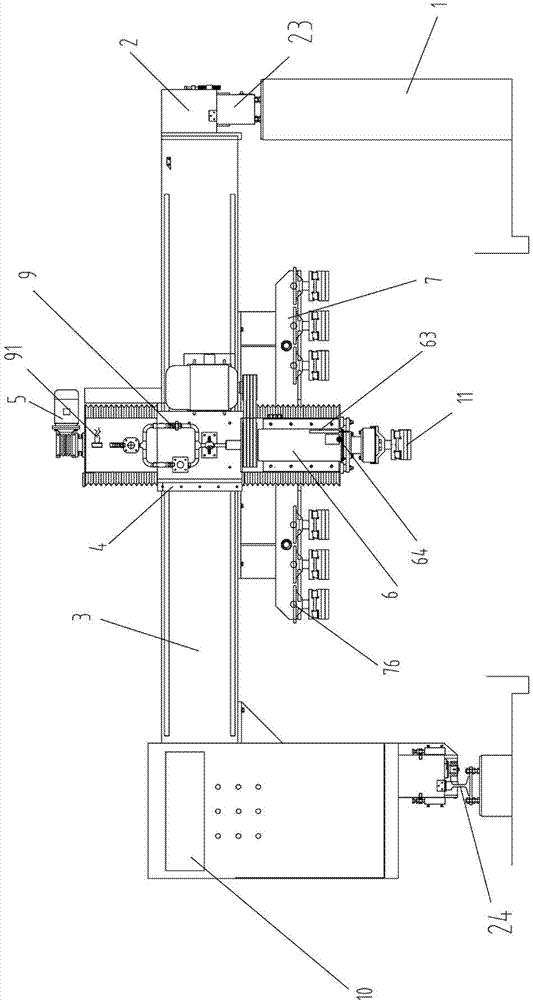
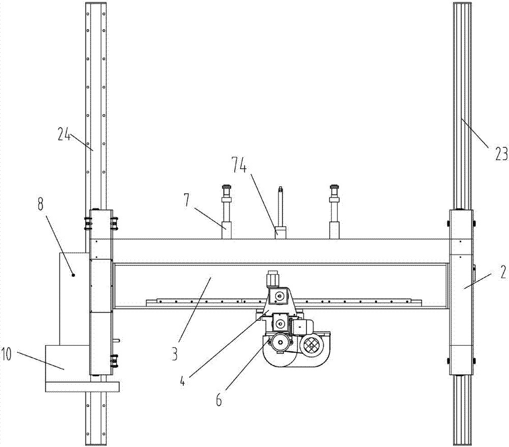
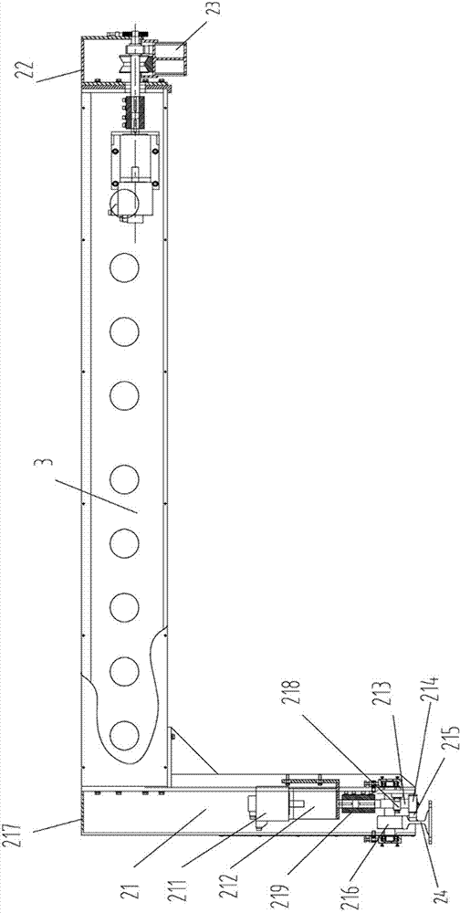
[0033] like figure 1 and figure 2 As shown, a fully automatic single-head grinding machine includes a frame 1, a vertical travel assembly, a traverse assembly 4, a lifting assembly 5, a spindle box assembly 6, a tool magazine 7, an air pressure control system 8, and a water supply. Assembly 9 and PLC intelligent control system 10; the rack 1 is a cement table, and the longitudinal travel assembly is installed on the rack; the longitudinal travel assembly includes two longitudinal travel parts, and the two longitudinal travel parts are respectively connected to the beam 3. Both ends are fixedly connected; the traverse assembly 4 is sleeved on the beam 3; the lifting assembly 5 is installed on the traverse assembly 4, and can move linearly along the beam guide with the traverse assembly; the knife The library 7 is fixed under the beam 3, and a plurality of grinding disc...


PUM


Abstract

The invention discloses a full-automatic single-head mill which comprises a frame, a longitudinal moving assembly, a transverse moving assembly, a lifting assembly, a spindle box assembly, a tool magazine, a pneumatic control system, a water supply assembly and a Programmable Logic Controller (PLC) intelligent control system. The longitudinal moving assembly is arranged on the frame and comprises two longitudinal moving portions and a beam, and the two longitudinal moving portions are respectively fixedly connected with two ends of the beam. The transverse moving assembly is arranged on the beam. The lifting assembly is erected on the transverse moving assembly. The tool magazine is fixed below the beam, and a plurality of millstones are arranged on the tool magazine. The spindle box assembly is fixedly arranged on the lifting assembly. The water supply assembly is connected with the spindle box assembly to supply cooling water. The PLC intelligent control system and the pneumatic control system are arranged on one side of the longitudinal moving assembly, and the PLC intelligent control system is connected with the longitudinal moving assembly, the transverse moving assembly, the lifting assembly, the spindle box assembly, the tool magazine, a pneumatic control system circuit and the water supply assembly.

Description

technical field [0001] The invention relates to the field of stone polishing machinery, in particular to a fully automatic single-head grinding machine. Background technique [0002] With the development of stone processing technology, the stone thickness determination and polishing technology have also made great progress, especially the stone polishing technology has developed from pure manual operation to automatic continuous polishing in the field of engineering boards, and the polishing quality is more reliable. , the production efficiency is greatly improved, and the labor intensity is greatly reduced, but the continuous polishing equipment is only suitable for batch polishing of stone materials with similar thickness, and the mechanical loading and unloading of grinding discs, and the manual control of cooling water flow greatly limits its polishing. The expansion of the grinding process also limits the surface polishing quality of the stone, and it is difficult to ac...

Claims


Application Information

Patent Timeline
Patent Type & Authority Applications(China)
IPC IPC(8): B24B19/22B24B55/02B24B41/04
Inventor 苏永定
Owner 厦门市盛达凯嘉机器有限公司
Learn More