Waste heat recovery device in steel wire heat treatment process
A waste heat recovery device and technology of heat treatment process, applied in heat treatment furnaces, heat treatment equipment, furnaces, etc., can solve the problems of increasing the temperature of the circulating water pool, ineffective utilization of heat energy, and affecting the cooling effect.
- Summary
- Abstract
- Description
- Claims
- Application Information
AI Technical Summary
Problems solved by technology
Method used
Image
Examples
Embodiment 1
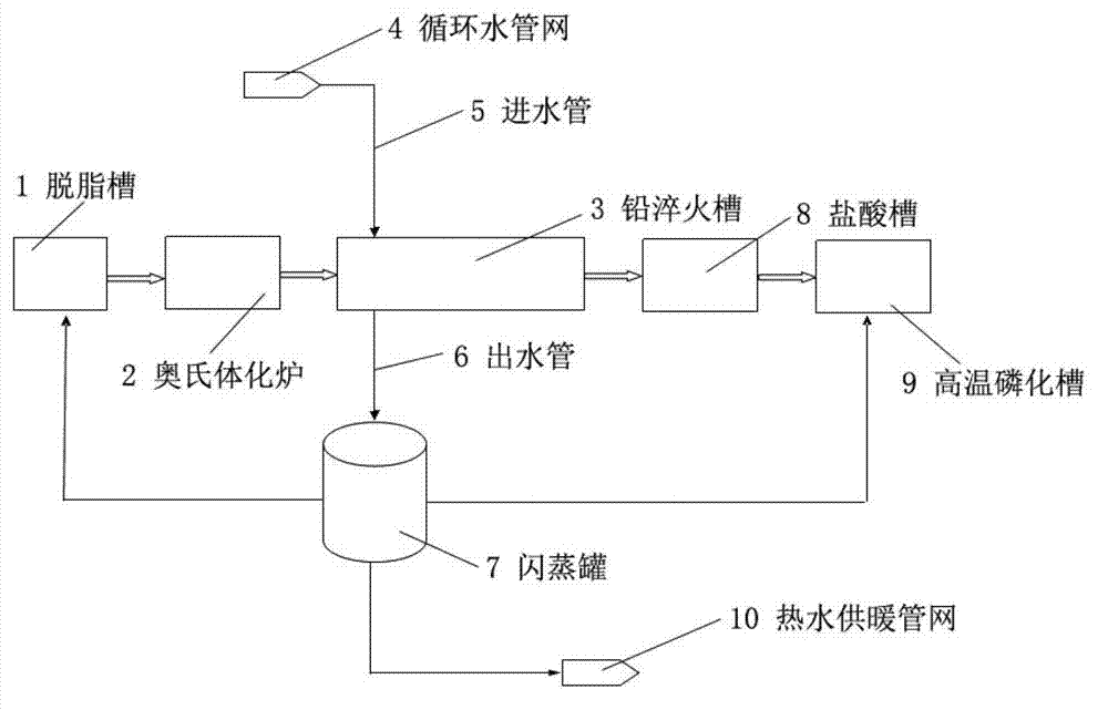
[0019] Such as figure 1 As shown, the circulating water from the circulating water pipe network 4 enters the superheating zone at the entrance of the quenching tank 3 from the water inlet pipe 5, and after cooling the superheated area, it enters the flash tank 7 from the water outlet pipe 6 and enters the high-pressure cooling circulating water in the flash tank 7 After entering the relatively low pressure flash tank 7 due to the sudden drop in pressure, the cooling circulating water becomes part of the saturated steam and saturated water under the vessel pressure. A part of the saturated steam after flashing from the flash tank 7 is sent to the degreasing tank 1 before the austenitizing furnace 2 for heating, and the other part is sent to the high temperature phosphating tank 9 after the hydrochloric acid tank 8 for heating. The saturated water is discharged from the flash tank 7 tank to the hot water heating pipe network 10, which can not only reduce the power consumption of ...
Embodiment 2
[0021] On the basis of the above embodiment, such as figure 1 As shown, a waste heat recovery device in the heat treatment process of steel wire includes a circulating water pipe network 4 connected to a quenching tank 3 through a water inlet pipe 5, and the quenching tank 3 is also provided with a water outlet pipe 6 connected to the flash tank 7, The flash tank 7 is also connected to the hot water heating pipe network 10, the lead quenching tank 3 is provided with an overheating zone, the lead quenching tank 3 is also provided with a cooling device, and the lead quenching tank 3 is also provided Precipitation filtering device, the flash tank 7 is also connected to the degreasing tank 1, the degreasing tank 1 is also connected to the austenitizing furnace 2, and the austenitizing furnace 2 is also connected to the lead quenching The lead quenching tank 3 is connected to the hydrochloric acid tank 8, the hydrochloric acid tank 8 is also connected to the high temperature phospha...
Embodiment 3
[0023] On the basis of the above embodiment, such as figure 1 As shown, a waste heat recovery device in the heat treatment process of steel wire includes a circulating water pipe network 4 connected to a quenching tank 3 through a water inlet pipe 5, so that circulating water enters the quenching tank 3 from the water inlet pipe 5; The lead quenching tank 3 is also provided with a water outlet pipe 6 connected to a flash tank 7, and the flash tank 7 is also provided with a hot water heating pipe network 10.
[0024] Wherein, the lead quenching tank 3 is provided with an overheating zone, a cooling device and a precipitation filtering device.
[0025] Wherein, while the circulating water cools the overheating zone, a cooling device is used to cool the overheating zone, and the precipitation device performs precipitation filtration on the circulating water.
[0026] Wherein, the flash tank 7 is a low-pressure flash tank.
[0027] Wherein, the flash tank 7 is further connected to the de...
PUM
 Abstract
Description
Claims
Application Information
 - R&D
- Intellectual Property
- Life Sciences
- Materials
- Tech Scout
- Unparalleled Data Quality
- Higher Quality Content
- 60% Fewer Hallucinations
Browse by: Latest US Patents, China's latest patents, Technical Efficacy Thesaurus, Application Domain, Technology Topic, Popular Technical Reports.
© 2025 PatSnap. All rights reserved.Legal|Privacy policy|Modern Slavery Act Transparency Statement|Sitemap|About US| Contact US: help@patsnap.com

