Airborne distributed inertial attitude measurement system and transfer alignment method of airborne distributed inertial attitude measurement system

A distributed, attitude measurement technology, applied in the field of inertial attitude measurement, can solve the problems of low precision, difficult to meet requirements, and accumulation of measurement errors, and achieve the effects of low cost, high integration and small size

Active Publication Date: 2013-07-10
NANJING UNIV OF SCI & TECH
View PDF2 Cites 36 Cited by
  • Summary
  • Abstract
  • Description
  • Claims
  • Application Information

AI Technical Summary

Problems solved by technology

[0003] If a high-precision IMU is installed at each sensor position, the accuracy can meet the requirements of long-term flight, but if six high-precision IMUs are installed, the cost will increase significantly, and the high-precision IMU must be too large to meet the requirements. The airborne system requires limited space; if only a low-cost, small-sized IMU is installed at each sensor position, due to its low accuracy, measurement errors accumulate over time, and the accuracy is difficult to meet the requirements

Method used


Image

  • Airborne distributed inertial attitude measurement system and transfer alignment method of airborne distributed inertial attitude measurement system
  • Airborne distributed inertial attitude measurement system and transfer alignment method of airborne distributed inertial attitude measurement system
  • Airborne distributed inertial attitude measurement system and transfer alignment method of airborne distributed inertial attitude measurement system

Examples


Embodiment 1

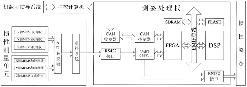
[0113] to combine Figure 5 , the hardware structure diagram of the transmission alignment sports car experiment of the airborne distributed inertial attitude measurement system of the present invention: the main and sub inertial guides are installed on an iron plate with a large installation error angle to simulate the installation position on the aircraft, The main inertial navigation system generates high-precision navigation parameters, which are sent to the main control computer at a certain frequency through the serial port. The main control computer converts the received navigation parameters into CAN bus data and sends them to the sub-inertial navigation system navigation computer, together with the sub-inertial navigation system Complete transfer alignment and output high-precision navigation information in real time.

[0114] In view of the fact that the installation error angle between the sub-inertial navigation system and the main inertial navigation system at dif...

Embodiment 2

[0117] Same as Embodiment 1, set the z-axis installation error angle compensation angle ξ z =32.5°, the installation error angle estimation curve of the second transfer alignment sports car experiment is as follows Figure 7 shown.

Embodiment 3

[0119] Same as Embodiment 1, the difference is that the z-axis installation error angle compensation angle ξ z =32°, the estimation curve of installation error angle in transfer alignment sports car experiment is as follows Figure 8 shown.


PUM


Abstract

The invention relates to an airborne distributed inertial attitude measurement system and a transfer alignment method of the airborne distributed inertial attitude measurement system. The airborne distributed inertial attitude measurement system comprises a master inertial navigation system, a main control computer, and six slave inertial navigation systems connected with the main control computer, wherein each slave inertial navigation system respectively comprises an inertial measurement unit and an attitude measurement processing board, each inertial measurement unit is connected with an RS_422 interface of the corresponding attitude measurement processing board, each RS_422 interface is connected with an FPGA (Field Programmable Gate Array) chip through a UART (Universal Asynchronous Receiver / Transmitter) control chip, each FPGA chip is connected with a DSP (Digital Signal Processor) chip through an EMIF (External Memory Interface) bus and also connected with the master inertial navigation system through a CAN (Control Area Network) controller and a CAN transceiver, and the main control computer is connected with the master inertial navigation system. The transfer alignment method between the master inertial navigation system and each slave inertial navigation system of the airborne distributed inertial attitude measurement system comprises the steps of: by taking the speed information error and the attitude information error of the master inertial navigation system and the slave inertial navigation systems as measuring variables, correcting speed information and attitude information calculated by the slave inertial navigation systems after carrying out Kalman filtering iteration, and finally obtaining stable and accurate navigation attitude information.

Description

1. Technical field [0001] The invention belongs to the technical field of inertial attitude measurement, in particular to an airborne distributed inertial attitude measurement system and a transfer alignment method thereof. 2. Background technology [0002] Facing the rapidly changing air situation, the pilot must find the target in the most agile way and choose the most effective way to attack. In order to enhance the pilot's field of vision and observation of the outside world, six optical sensors for imaging are installed on the aircraft to provide a 360° full-dimensional situational awareness capability, and ultimately be able to collect various information within a 360° range. However, the line of sight of the optical detector used for imaging must produce a certain degree of random jitter with the vibration of the carrier. This kind of vibration will cause obvious shaking of the image, and it will also have a great impact on the image stitching between several detecto...

Claims


Application Information

Patent Timeline
Patent Type & Authority Applications(China)
IPC IPC(8): G01C21/16G01C25/00
Inventor 陈帅李玺安王于坤张黎王磊杰邓贵军薄煜明杜国平邹卫军吴盘龙常耀伟钟润伍金磊单童雷浩然程晨马艳彬秦磊
Owner NANJING UNIV OF SCI & TECH
Why Eureka
Try Eureka