Ultrahigh frequency sensor for cable partial discharge online monitoring

An ultra-high frequency sensor, partial discharge technology, applied in the direction of testing dielectric strength, etc., can solve the problem of low transmission loss of ultra-wideband non-frequency-variable antenna, and achieve to overcome large signal attenuation, good standing wave characteristics, and overcome low-frequency characteristics. bad effect

Inactive Publication Date: 2013-07-10
HARBIN UNIV OF SCI & TECH +2
View PDF6 Cites 9 Cited by
  • Summary
  • Abstract
  • Description
  • Claims
  • Application Information

AI Technical Summary

Problems solved by technology

[0006] The purpose of the present invention is to solve the problem that the existing ultra-wideband non-frequency-variable antenna cannot have both small transmission loss and low-frequency end characteristics, and provides an ultra-high frequency sensor for on-line monitoring of cable partial discharge

Method used


Image

  • Ultrahigh frequency sensor for cable partial discharge online monitoring
  • Ultrahigh frequency sensor for cable partial discharge online monitoring
  • Ultrahigh frequency sensor for cable partial discharge online monitoring

Examples


specific Embodiment approach 1

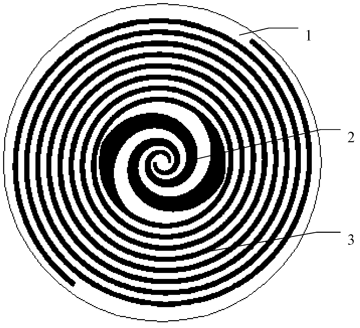
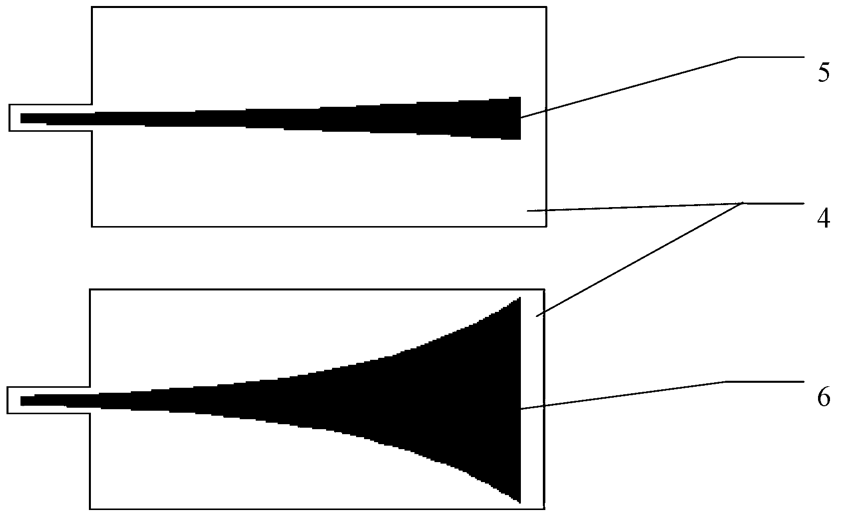
[0021] Specific implementation mode one: the following combination figure 1 , figure 2 , Figure 4 and Figure 5 Describe this embodiment, the ultra-high frequency sensor used for cable partial discharge on-line monitoring described in this embodiment, it includes antenna substrate 1, equiangular helical antenna section 2, Archimedes antenna section 3, microstrip line substrate 4, Center conduction strip microstrip line 5 and ground plate microstrip line 6,

[0022] An equiangular helical antenna section 2 and an Archimedes antenna section 3 are spirally arranged in turn on the antenna substrate 1 from the center to the outer ring direction, and the two ends of the equiangular helical antenna section 2 are connected to the two ends of the Archimedes antenna section 3. Head-end one-to-one correspondence connection;

[0023] The center of the head end side of the microstrip line substrate 4 has a protruding rectangular connecting column. The front center of the microstrip l...

specific Embodiment approach 2

[0030] Specific implementation mode two: the following combination Figure 1 to Figure 3 Describe this embodiment, this embodiment will further explain Embodiment 1, the initial helix angle of the equiangular helical antenna section 2 in this embodiment is 0 degrees, the end helix angle is 3π to 4π, and the Archimedes antenna section 3 The starting helix angle is 3π to 4π, and the ending helix angle is 11π to 12π.

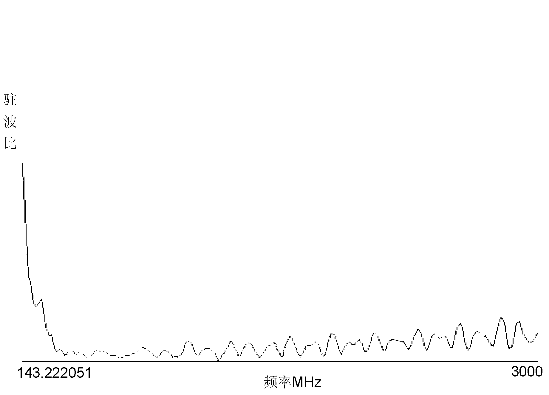
[0031] Using the electromagnetic simulation software Ansoft HFSS to simulate the ultra-high frequency sensor, through a large number of simulation optimization of the antenna's spiral start and stop radius, the length of the impedance matching plate and the width of the head and end, it can be concluded that in the designed frequency band, that is, 300MHz In the range of -3GHz, the parameter values ​​that make the standing wave ratio of the sensor reach the minimum value.

[0032] image 3 Shown is the actual measurement result of the standing wave characteristic...


PUM


Abstract

The invention discloses an ultrahigh frequency sensor for cable partial discharge online monitoring, and belongs to the technical field of cable terminal discharge monitoring. The ultrahigh frequency sensor for the cable partial discharge online monitoring solves the problem that an existing ultra wide band frequency-independent antenna can not have the characteristics of being low in transmission loss and ensuring a low frequency end at the same time. The ultrahigh frequency sensor for the cable partial discharge online monitoring comprises an antenna substrate, an equiangular helical antenna section, an Archimedes antenna section, a micro-strip line substrate, central conduction band micro-strip lines and earth plate micro-strip lines, wherein the equiangular helical antenna section and the Archimedes antenna section are spirally arranged on the antenna substrate from the center to the direction of an outer ring in sequence, two tail ends of the equiangular helical antenna section are correspondingly connected with two head ends of the Archimedes antenna section in a one-to-one mode, a protruding rectangular connecting column is arranged in the center of a head end side of the micro-strip line substrate, the central conduction band micro-strip lines cover the center of the obverse side of the micro-strip line substrate from the head end to the tail end, and the earth plate micro-strip lines cover the center of the reverse side of the micro-strip line substrate from the head end to the tail end. The ultrahigh frequency sensor for the cable partial discharge online monitoring is used for online monitoring of ultrahigh frequency signals of cable partial discharge.

Description

technical field [0001] The invention relates to an ultra-high frequency sensor for on-line monitoring of cable partial discharge, belonging to the technical field of cable terminal discharge monitoring. Background technique [0002] Partial discharge is one of the main causes of power cable insulation failure. Due to the complexity and imperfection of the cable terminal insulation, the incidence of partial discharge is much higher than that of the cable body. Partial discharge monitoring of cable terminals is of great significance to ensure the safe and reliable operation of cable lines. [0003] The partial discharge pulse time at the cable terminal is extremely short, usually on the order of nanoseconds. This discharge pulse will excite high-frequency electromagnetic signals. A large number of studies have shown that the frequency band of electromagnetic signals excited by partial discharge is concentrated in the 300MHz-3GHz. If you want to receive such a broadband The e...

Claims


Application Information

Patent Timeline
Patent Type & Authority Applications(China)
IPC IPC(8): G01R31/12
Inventor 张晓虹高俊国张新魁郭宁王国利刘通王颂李锐海刘智宏王剑英臧源源黄小卫
Owner HARBIN UNIV OF SCI & TECH
Why Eureka
Try Eureka