System and method for numerical control (NC) workbench error self correction based on machine vision

A technology of machine vision and workbench, which is applied in the field of self-calibration system, can solve problems such as difficulty in guaranteeing accuracy, cumbersome correction work, and inability of grating or encoder to perform effective compensation, so as to improve positioning accuracy, system positioning accuracy, and high efficiency Effect

Inactive Publication Date: 2013-07-10
DONGHUA UNIV
View PDF4 Cites 63 Cited by
  • Summary
  • Abstract
  • Description
  • Claims
  • Application Information

AI Technical Summary

Problems solved by technology

The traditional method to ensure positioning accuracy is to use a rotary encoder as a positioning feedback device, but it cannot compensate errors due to uneven lead screw lead and backlash.
The use of linear grating feedback can make up for this loss of accuracy to a certain extent, but due to the expansion or contraction of the workbench or grating affected by temperature, or the perpendicularity of the X-axis and Y-axis during installation, positioning errors will be introduced into the system. Cannot be effectively compensated by grating or encoder
[0003] The traditional method of correcting the above errors is to use a laser interferometer for correction. The correction work is very cumbersome, and due to system handling or other reasons, repeated corrections are required, and the accuracy is difficult to guarantee.

Method used


Image

  • System and method for numerical control (NC) workbench error self correction based on machine vision
  • System and method for numerical control (NC) workbench error self correction based on machine vision
  • System and method for numerical control (NC) workbench error self correction based on machine vision

Examples


Embodiment Construction

[0036] In order to make the present invention more comprehensible, a preferred embodiment is described in detail below with accompanying drawings.

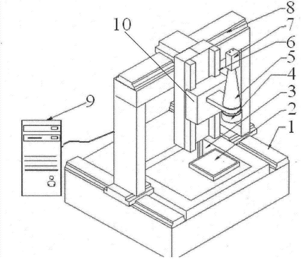
[0037] figure 1 A schematic diagram of a CNC workbench error self-correction system based on machine vision provided by the present invention. The machine vision-based CNC workbench error self-correction system includes an X, Y, Z three-coordinate motion workbench, a moving body 10 is placed on the X, Y, Z three-coordinate motion workbench, an image acquisition system is installed on the motion body 10, and objects with rich surface or contour features are placed on the stage 3 of the X, Y, Z three-coordinate motion workbench. The calibration board 2 is used by the industrial computer 9 to analyze and calculate the sequence images collected by the image acquisition system to obtain the positioning error of each coordinate on the X-Y plane.

[0038] The X, Y, Z three-coordinate motion workbench includes a stage 3, and the two side...


PUM


Abstract

The invention provides a system for numerical control (NC) workbench error self correction based on machine vision. The system comprises an X-Y-Z-coordinate motion workbench, an image collecting system is arranged on a motion body of the X-Y-Z-coordinate motion workbench, a calibration plate is arranged on an objective table of the X-Y-Z-coordinate motion workbench, and an industrial computer is connected with the image collecting system. The invention further provides a method for NC workbench error self correction based on the machine vision. The method comprises the following steps: controlling the motion body and a high-resolution industrial camera to move, and collecting sequential images; obtaining a current absolute coordinate according to the imaging data of the motion body at different positions, comparing with a movement directive the encoder feedback value of a servo motor, and obtaining positioning error compensation values; and continuously conducting positioning detecting at different positions, and enabling the positioning error compensation values of all positions to be stored into a databank. According to the system and the method for NC workbench error self correction based on the machine vision, the defects of the prior art are overcome, self calibration and compensation can be conducted to the X-Y positioning error of the whole workbench, and positioning accuracy is markedly improved.

Description

technical field [0001] The invention relates to a machine vision-based self-correction system and method for X-Y plane positioning errors of a numerical control workbench, belonging to the technical field of three-coordinate motion workbenches. Background technique [0002] Three-coordinate motion workbenches are generally used as automation devices in modern manufacturing, and the positioning accuracy of its X-Y plane motion determines the performance of the device and the accuracy of processing and testing. The traditional method to ensure positioning accuracy is to use a rotary encoder as a positioning feedback device, but it cannot compensate errors due to uneven lead screw lead and backlash. The use of linear grating feedback can make up for this loss of accuracy to a certain extent, but due to the expansion or contraction of the workbench or grating affected by temperature, or the perpendicularity of the X-axis and Y-axis during installation, positioning errors will be...

Claims


Application Information

Patent Timeline
Patent Type & Authority Applications(China)
IPC IPC(8): G05B19/19
Inventor 周虎谈高超李月林夕腾
Owner DONGHUA UNIV
Why Eureka
Try Eureka