
High-capacity medium voltage battery energy storage system

A battery energy storage system and large-capacity technology, applied in the field of electric energy storage, can solve the problems of high anti-saturation requirements, unfavorable stable operation, and high difficulty in control, and achieve low voltage withstand requirements, low battery cell capacity requirements, and maintainability good sex effect

Inactive Publication Date: 2013-07-10
中国南方电网有限责任公司调峰调频发电公司 +1
View PDF3 Cites 12 Cited by
  • Summary
  • Abstract
  • Description
  • Claims
  • Application Information

AI Technical Summary

Problems solved by technology

Its shortcoming is that the amplitude and phase of the three-phase voltage need to be properly controlled when the energy storage system performs phase-to-phase balance and fault redundancy control, but the control of the three-phase voltage is mutually coupled, and the control is difficult, which is not conducive to its stable operation
[0007] In a device similar to a chain structure, the primary side grid connection adopts a centralized connection reactance. Due to the structural layout, considering the possible short circuit between the lower end of the reactance directly to the ground / phase to phase, the connection reactance needs to be in accordance with the direct short circuit resistance. Power design, high cost, large volume, high anti-saturation requirements

Method used

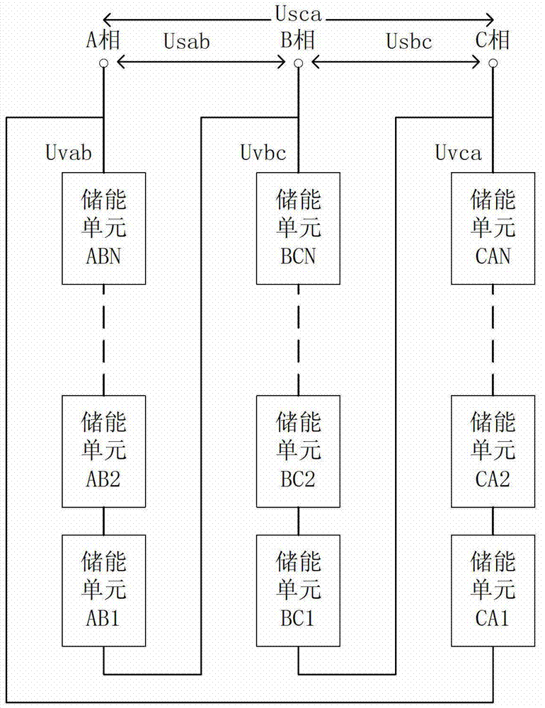

Image

  • High-capacity medium voltage battery energy storage system
  • High-capacity medium voltage battery energy storage system
  • High-capacity medium voltage battery energy storage system

Examples


Embodiment

[0024] This embodiment is a 2MW*2h battery energy storage system with a rated voltage of 10kV.

[0025] Such as image 3 As shown, the energy storage unit of this embodiment includes: 1 battery pack, 1 resistor, 1 contactor, 1 set of capacitors, 4 IGBTs and 1 connection reactance. A, B, C three-phase 20 energy storage units each, according to figure 2 The way of connection constitutes the entire medium-voltage energy storage system.

[0026] In this embodiment, the rated voltage of one storage battery unit is 960V, and the nominal capacity is 200Ah.

[0027] In this embodiment, the pre-charging circuit is composed of a resistor R1 and a contactor K1. Among them: Resistor R1 and contactor K1 are connected in parallel. One end of the resistor R1 and the contactor K1 is connected to the positive pole of the battery pack, which is the input end of the pre-charging circuit; the other end of the resistor R1 and the contactor K1 is the output end of the pre-charging circuit. Th...


PUM


Abstract

The invention discloses a high-capacity medium voltage battery energy storage system. An output end of an energy storage battery unit is connected with an input end of a pre-charging circuit to transfer a direct current voltage, an output end of the pre-charging circuit is connected with a direct current end of a single phase H bridge converter to transfer the direct current voltage, and an output end of the single phase H bridge converter is connected with a reactor in series. Therefore, one energy storage unit is formed, alternating current sides of a plurality of energy storage units are connected in series and then are connected with a connection inductor in series to form a branch circuit, three branch circuits are connected in an end-to-end mode to form a triangular connection, and then three endpoints of the triangular are connected with a medium voltage power grid in a three-phase mode. A grid inductor is formed by connecting of inductors of all energy storage units in series, the effect of single inductor fault on the system is small, and reliability is high. Under the same power, the high-capacity medium voltage battery energy storage system is high in voltage, small in current and current harmonics and low in demands on single capacity of a battery. Redundancy can be realized through a bypath, and reliability is high. The high-capacity medium voltage battery energy storage system has a balancing function on the battery. Compared with a medium voltage energy storage system of primary side star connection, the high-capacity medium voltage battery energy storage system is easy to control and high in reliability.

Description

technical field [0001] The invention relates to a large-capacity medium-voltage energy storage system, in particular to a modular AC cascaded structure energy storage system, which is used for large-capacity battery energy storage applications. It belongs to the field of electric energy storage. Background technique [0002] The use of battery energy storage systems to smooth wind power and photovoltaic power generation is an effective way to solve the problem of new energy grid connection and wind power "abandonment". The application of large-capacity electric energy storage in the power grid has changed the history that electric energy can only be transmitted but not stored, has brought a revolutionary impact on the production and operation of the power grid, and greatly promoted the development of my country's smart grid. [0003] The battery energy storage system uses a DC / AC bidirectional power converter to realize the bidirectional flow of power between the battery an...

Claims


Application Information

Patent Timeline
IPC IPC(8): H02J15/00
Inventor 郭海峰凌志斌李永兴张百华李勇琦陈满
Owner 中国南方电网有限责任公司调峰调频发电公司
Learn More