Stator permanent magnetic flux-switching bearing-free motor with E-shaped teeth

A bearingless motor, magnetic flux switching technology, applied in synchronous machines, electrical components, electromechanical devices, etc., can solve the problems of heat dissipation and mechanical robustness that cannot be ignored, efficiency and power factor are not as good as permanent magnet motors, and permanent magnet utilization rate is reduced. and other problems, to achieve high reliability, ability to operate with faults, compact structure, and high power density.

Inactive Publication Date: 2013-07-10
SOUTHEAST UNIV
View PDF4 Cites 24 Cited by
  • Summary
  • Abstract
  • Description
  • Claims
  • Application Information

AI Technical Summary

Problems solved by technology

However, the existing bearingless permanent magnet synchronous motors with traditional rotor permanent magnet structure have certain limitations: on the one hand, the permanent magnets mounted on the rotor surface or embedded in the rotor destroy the overall structure of the rotor, while as For high-speed motors, the rotors are usually in a high-speed or even ultra-high-speed operating state (tens of thousands of revolutions per minute or even hundreds of thousands of revolutions per minute). Fixing devices made of stainless steel or metal fiber materials lead to complex structures, increased manufacturing costs, long equivalent air gaps, and reduced utilization of permanent magnets; As the temperature rises, the performance of the permanent magnet mainly compose

Method used


Image

  • Stator permanent magnetic flux-switching bearing-free motor with E-shaped teeth
  • Stator permanent magnetic flux-switching bearing-free motor with E-shaped teeth
  • Stator permanent magnetic flux-switching bearing-free motor with E-shaped teeth

Examples


Embodiment Construction

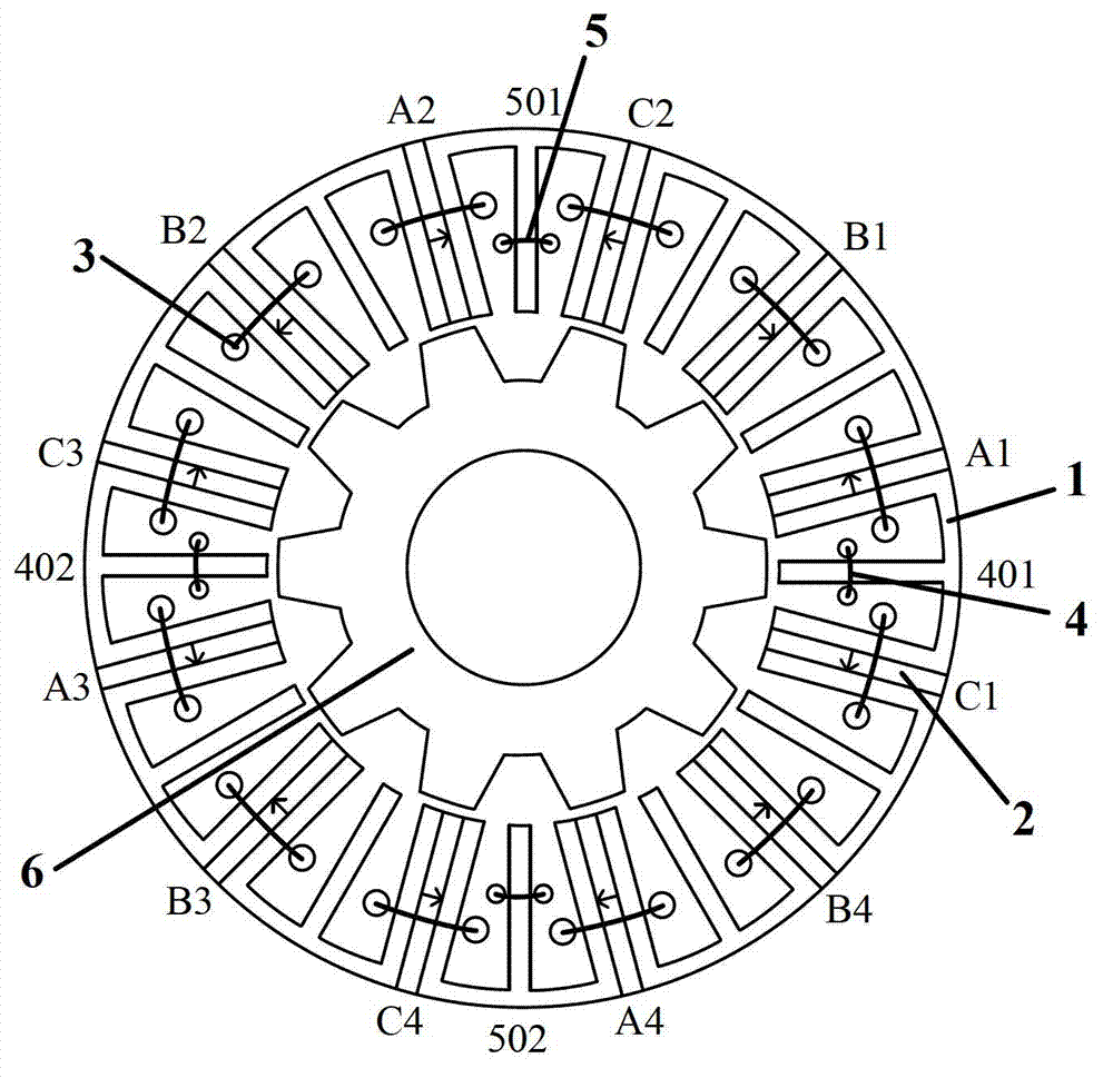
[0032] see figure 1 , the stator permanent magnet flux switching bearingless motor of the present invention includes a stator 1 and a rotor 6, the rotor 6 is located inside or outside the stator 1, both the stator 1 and the rotor 6 are salient pole structures, and the stator 1 is provided with a three-phase symmetrical centralized Type armature winding 3, X-axis suspension winding 4, Y-axis suspension winding 5 and permanent magnet 2.

[0033] Taking a three-phase stator 12-pole / rotor 10-pole stator permanent magnet flux switching bearingless motor as an example, its cross-sectional view is as follows figure 1 As shown, there are 12 uniformly distributed armature tooth core units and 12 uniformly distributed fault-tolerant teeth on the stator, the armature tooth core units and fault-tolerant teeth are distributed alternately, and there are 10 uniformly distributed salient poles on the rotor; the stator core consists of Composed of 12 "E" type magnetic core units, a tangential...


PUM


Abstract

The invention discloses a stator permanent magnetic flux-switching bearing-free motor with E-shaped teeth. The stator permanent magnetic flux-switching bearing-free motor with the E-shaped teeth comprises a stator and a rotor. The stator comprises E-shaped permeance iron cores, permanent magnets, a concentrated armature winding and a set of concentrated floating windings. The concentrated floating windings, the armature winding and the permanent magnets are arranged in the stator. A stator permanent magnetic doubly-salient structure is used, a stator iron core is formed by assembling the permeance iron cores with an E-shaped cross section and the permanent magnets arranged among the permeance iron cores. Openings of the E-shaped permeance iron cores face gaps and evenly distributed on a ring. The permanent magnets undergo tangential magnetizing and magnetizing directions of two adjacent permanent magnets are opposite. Fault-tolerance teeth provide magnetic return paths for the permanent magnets and the armature winding. The armature winding transversely span on two sides of an armature tooth iron core unit of the stator. One set of the floating windings are composed of two sets of floating coils. Two sets of the floating coils are respectively wound on the fault-tolerance teeth of the X axlix direction and the Y axis direction. The stator permanent magnetic flux-switching bearing-free motor with the E-shaped teeth is simple in structure like a bearing-free switch reluctance motor and has high efficiency and high power density like a bearing-free rotor permanent magnetic motor.

Description

technical field [0001] The invention belongs to the technical field of motor manufacturing, in particular to a stator permanent magnet type bearingless motor. Background technique [0002] In the fields of high-speed drive, sealed transmission and aerospace, there is an urgent need for the bearingless operation technology of the motor. Due to the many limitations of mechanical bearings, ordinary motors cannot meet the requirements of long-term high-speed operation; the control equipment of air-floating and liquid-floating bearings is relatively large and the cost is high; magnetic suspension bearings have no mechanical wear, no lubrication and sealing systems, and strong environmental adaptability, etc. However, the overall structure of the magnetic bearing motor system is relatively complex, the power density is not high, and the critical speed and power capacity are difficult to greatly increase. In 1985, the emergence of fast and load-capable power switching devices and ...

Claims


Application Information

Patent Timeline
IPC IPC(8): H02K21/00H02K21/04H02K1/17H02K1/14H02N15/00
Inventor 花为邵凌云程明
Owner SOUTHEAST UNIV
Why Eureka
Try Eureka