Non-contact temperature measurement device and temperature measurement method thereof

A temperature measurement, non-contact technology, applied in measuring devices, thermometers with directly heat-sensitive electric/magnetic elements, thermometers, etc., can solve the problems of increasing the volume of temperature sensors, affecting accuracy, and fewer sampling points

Active Publication Date: 2013-07-17
ZHEJIANG UNIV
View PDF8 Cites 13 Cited by
  • Summary
  • Abstract
  • Description
  • Claims
  • Application Information

AI Technical Summary

Problems solved by technology

However, this measurement method has certain limitations: first, in this measurement method, the DSP uses its own A / D sampling unit to sample the conditioned signal, but the A / D sampling unit of the DSP itself is subject to the main frequency of the DSP. When the high-frequency signal is sampled, the number of sampling points is too small, it is not easy to obtain the required voltage amplitude, which has a certain impact on the calculation of the temperature value; secondly, when measuring the temperature and voltage signal cycle, because the signal frequency is high, it is not easy to use DSP directly. The accurate signal period is measured, which will inevitably affect the accuracy and resolution of the calculated temperature; in addition, because this method directly calculates the sampled voltage information in the time domain, the sampled voltage itself is small and is susceptible to noise and parasitic parameters. Influenced by interference, the collected voltage will be disturbed, which will also affect the accuracy of the calculation; finally, the temperature sensor in the system uses a thermistor, which not only increases the volume of the temperature sensor, but also in order to be able to sample enough decaying voltage waveforms, The inductor volume must also be large; these factors are not conducive to placing the sensor in an application where the sensor volume is sensitive

Method used


Image

  • Non-contact temperature measurement device and temperature measurement method thereof
  • Non-contact temperature measurement device and temperature measurement method thereof
  • Non-contact temperature measurement device and temperature measurement method thereof

Examples


Embodiment Construction

[0059] In order to describe the present invention more specifically, the measuring system and its measuring method of the present invention will be described in detail below in conjunction with the accompanying drawings and specific embodiments.

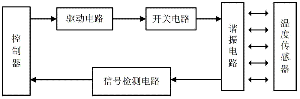
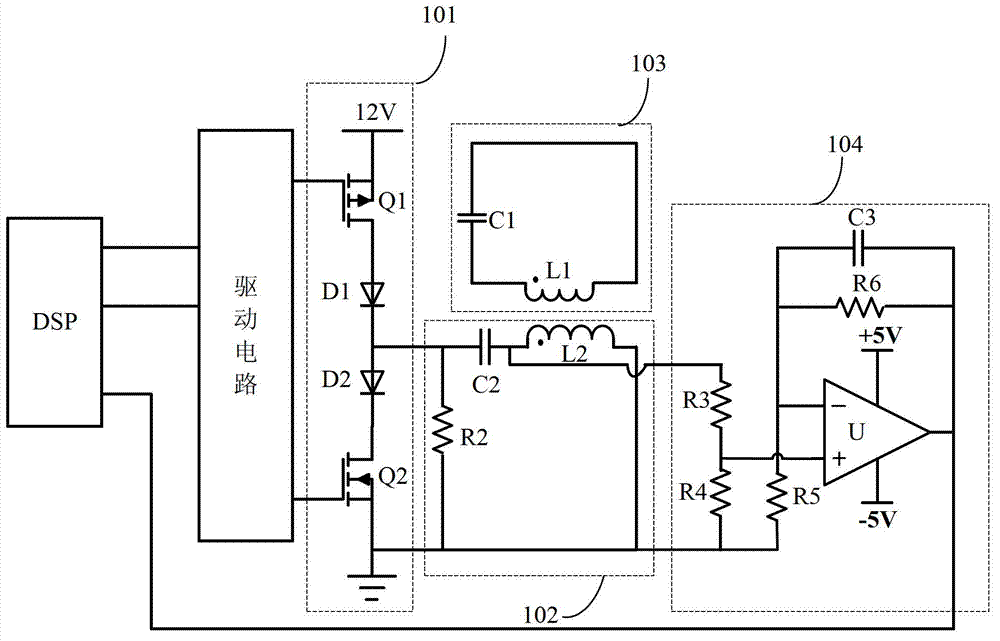
[0060] Such as figure 1 and figure 2 As shown, a non-contact temperature measurement device includes: a controller, a drive circuit, a switch circuit 101 , a resonant circuit 102 , a signal detection circuit 104 and a temperature sensor 103 .

[0061] The driving circuit is connected to the controller, which amplifies the two driving signals provided by the controller and then outputs it; in this embodiment, the driving circuit adopts the IRF2110 chip of International Rectifier Company.

[0062] The switch circuit 101 is connected with the drive circuit, and outputs a square wave signal according to the two amplified drive signals provided by the drive circuit; in this embodiment, the switch circuit 101 is composed of two MOS trans...


PUM


Abstract

The invention discloses a non-contact temperature measurement device which comprises a controller, a driving circuit, a switching circuit, a resonance circuit, a temperature sensor and a signal detection circuit. Inductance and circuit internal resistance serve as resonant resistance of the temperature sensor, the resistance is small, and therefore the attenuation rate of temperature voltage signals is small during resonance, a plurality of periodic attenuation sinusoidal temperature voltage signals can be generated, and simultaneously device volume is correspondingly reduced. The invention further discloses a temperature measurement method of the non-contact temperature measurement device. The temperature measurement method is characterized in that a sampling signal differential equation is not needed to be solved due to the fact that discrete Fourier transformation is adopted as the basis, and computer analytical calculation is facilitated; and in frequency-domain analysis, the effective signal frequency and the useless interference signal frequency can be separated, frequency-domain analysis is visual in aspect of the physical meaning, signal interference can be reduced as far as possible, and further analysis and process are facilitated.

Description

technical field [0001] The invention belongs to the technical field of temperature measurement, and in particular relates to a non-contact temperature measurement device and a temperature measurement method thereof. Background technique [0002] In daily life and industrial production process, it is often necessary to measure the temperature of various objects. Temperature is a very important index parameter in many technical fields. In many fields such as industry, medical treatment, military affairs and life, temperature measuring devices are required to monitor temperature. The automatic monitoring of temperature has become one of the important measures for safe production and loss reduction in all walks of life. In certain occasions, due to the scattered and remote monitoring points, the traditional temperature measurement method has a long period and high cost, and the surveyor must go to the site to measure, so the work efficiency is very low. [0003] Temperature me...

Claims


Application Information

Patent Timeline
Patent Type & Authority Applications(China)
IPC IPC(8): G01K7/18
Inventor 吴建德赵崇文何湘宁黄强
Owner ZHEJIANG UNIV
Why Eureka
Try Eureka