Filtering reactance level and variable frequency driving system using same

A technology of variable frequency drive and filter reactance, which is applied in the field of filter reactance and can solve problems such as limited effect of common mode current suppression

Inactive Publication Date: 2013-07-17
DELTA ELECTRONICS INC
View PDF5 Cites 4 Cited by
  • Summary
  • Abstract
  • Description
  • Claims
  • Application Information

AI Technical Summary

Problems solved by technology

However, traditional inductors have lim

Method used


Image

  • Filtering reactance level and variable frequency driving system using same
  • Filtering reactance level and variable frequency driving system using same
  • Filtering reactance level and variable frequency driving system using same

Examples


Embodiment Construction

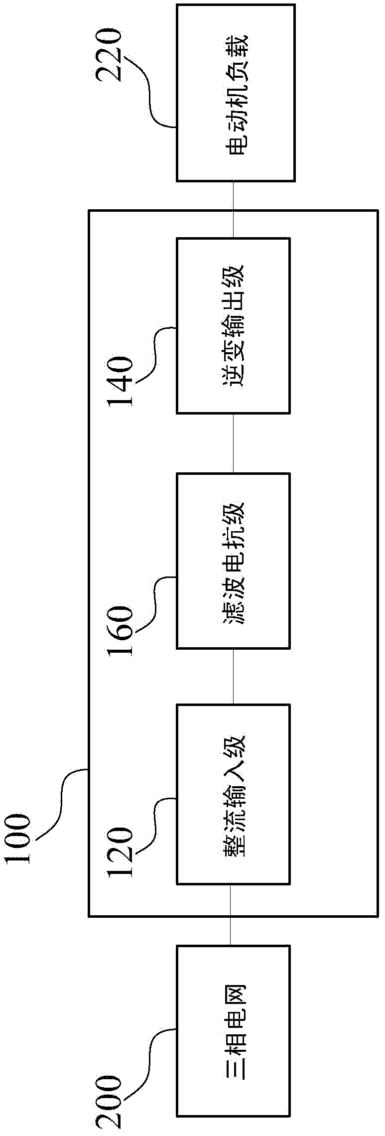
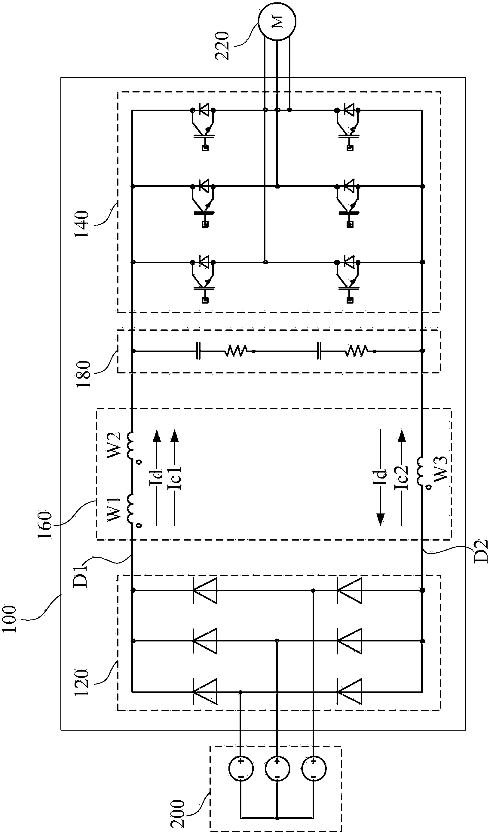
[0046] see figure 1 , which is a functional block diagram of a variable-frequency drive (Variable-frequency Drive, VFD) system 100 in a preferred embodiment of the present invention. Such as figure 1 As shown, the variable frequency drive system 100 includes a rectifier input stage 120 , an inverter output stage 140 and a filter reactance stage 160 .

[0047] In this preferred embodiment, the variable frequency drive system 100 can receive an AC input voltage with a fixed operating frequency from the three-phase grid 200, adjust the frequency and amplitude of the AC input voltage, and then use the adjusted AC output voltage to drive an external motor load 220 (such as an induction motor), in this way, the rotational speed of the motor load 220 can be smoothly controlled.

[0048] As mentioned above, the rectifier input stage 120 is electrically connected to the three-phase grid 200 . The rectifying input stage 120 is used to convert the AC input voltage with a fixed operati...


PUM


Abstract

The invention discloses a filtering reactance level and a variable frequency driving system using same. The variable frequency driving system using the filtering reactance level comprises a rectifying input level, an inverter output level and a filtering reactance level. The filtering reactance level which is coupled between the rectifying input level and the inverter output level and comprises a magnetic core module, a first winding group, a second winding group and a third winding group. The magnetic core module comprises a middle column, a first edge column and a second edge column. The first winding group is wound on the first edge column, the second winding column is wound on the second edge column, and the first winding group and the second winding group are in series connection with a first direct current arm which is arranged between the rectifying input level and the inverter output level. The third winding group is wound on the middle column and two ends of the third winding group are in series connection with a second direct current arm between the rectifying input circuit and the inverter output circuit. The three winding groups of the filtering reactance level are capable of supplying enough common mode choke to restrain common mode currents and form adjustable different mode inductance to reduce energy loss of a filtering reactance.

Description

technical field [0001] The present invention relates to a filter reactance stage, and in particular to a filter reactance stage applied in a variable frequency drive system. Background technique [0002] In the control of electric machines or induction motors, motor speed regulation is an important issue. The traditional DC speed control technology used in existing electric machines is limited in its application due to its large hardware size and high failure rate. [0003] Inverter (Variable-frequency Drive, VFD) applies frequency conversion technology and electronic active component technology to control the output of the AC motor by changing the frequency and amplitude of the working power from the input terminal. [0004] The function of the frequency converter is to change the frequency and amplitude of the AC power supplied to the induction motor, and further change the period of its moving magnetic field, so as to achieve the purpose of smoothly controlling the speed ...

Claims


Application Information

Patent Timeline
IPC IPC(8): H02M1/44
Inventor 萧伟成
Owner DELTA ELECTRONICS INC
Why Eureka
Try Eureka