Automatic detection and compensation device and method for installation errors of Hall position sensor of motor

A technology of Hall position and installation error, applied in the field of automatic detection and compensation device for installation error of motor Hall position sensor, can solve problems such as poor versatility, complex engineering implementation, and reduced control system efficiency.

Inactive Publication Date: 2013-07-17
XIAN UNIV OF SCI & TECH
View PDF3 Cites 23 Cited by
  • Summary
  • Abstract
  • Description
  • Claims
  • Application Information

AI Technical Summary

Problems solved by technology

However, like other types of sensors, the assembly error of the Hall rotor position sensor during installation will cause an error between the actual rotor position of the motor and the rotor position detected by the Hall sensor. Expected and uncontrollable direct-axis current, which affects the accuracy of motor control and reduces the efficiency of the control system. In severe cases, the motor cannot be started or reversed
[0003] At present, the detection of the installation error of the Hall-type motor rotor position sensor usually uses manual experiments to adjust the installation position of the Hall position sensor until the accuracy requirements are met, which is costly and inefficient.
Some people have also proposed the back EMF method to detect the installation error of the Hall-type motor rotor position sensor, but the size of the back EMF method is related to the motor speed, and its versatility is poor; in addition, in order to obtain a relatively smooth back EMF waveform, the back EMF signal The filter is usually introduced during the detection of the signal, which causes the phase angle delay and amplitude attenuation of the signal, and additional compensation processing is required, and the engineering implementation is complicated

Method used


Image

  • Automatic detection and compensation device and method for installation errors of Hall position sensor of motor
  • Automatic detection and compensation device and method for installation errors of Hall position sensor of motor
  • Automatic detection and compensation device and method for installation errors of Hall position sensor of motor

Examples


Embodiment Construction

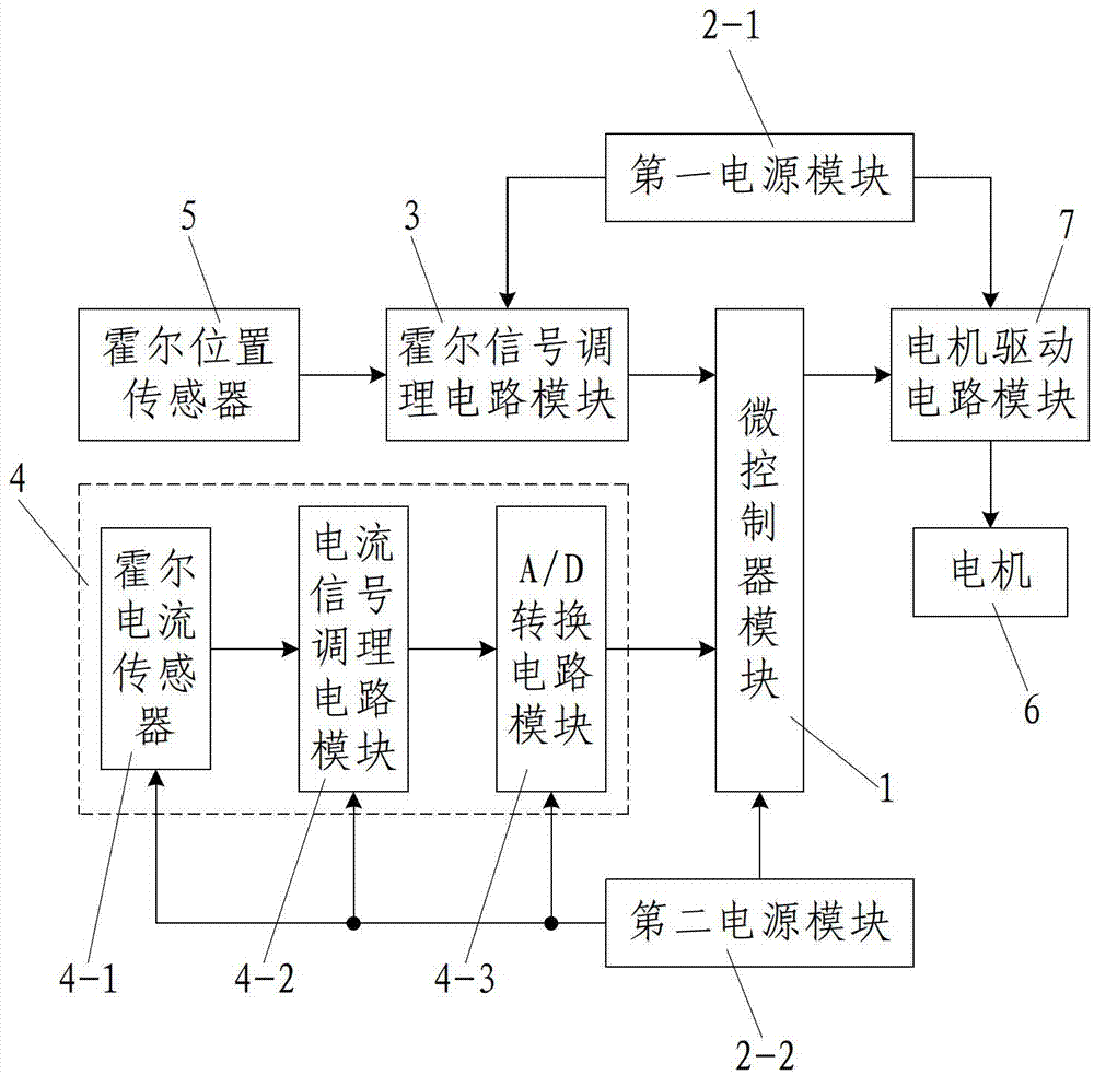
[0055] Such as figure 1 As shown, the installation error automatic detection and compensation device of the motor Hall position sensor according to the present invention includes a microcontroller module 1 and a power supply module for supplying power to each power module in the device, and the input terminal of the microcontroller module 1 Connected with the Hall signal conditioning circuit module 3 for conditioning the signal output by the Hall position sensor 5 installed on the motor 6 and the motor winding current detection circuit module 4 for detecting the winding current of the motor 6, the motor The winding current detection circuit module 4 is composed of a Hall current sensor 4-1, a current signal conditioning circuit module 4-2 and an A / D conversion circuit module 4-3 connected in sequence, and the A / D conversion circuit module 4-3 It is connected with the input end of the microcontroller module 1 , and the output end of the microcontroller module 1 is connected wit...


PUM


Abstract

The invention discloses an automatic detection and compensation device and method for installation errors of a Hall position sensor of a motor. The device comprises a micro-controller module and a power supply module, wherein the input end of the micro-controller module is connected with a Hall signal conditioning circuit module and a motor winding current detection circuit module; the motor winding current detection circuit module is composed of a Hall current sensor, a current signal conditioning circuit module and an A / D (Analog-to-digital) conversion circuit module which are connected in sequence; the A / D conversion circuit module is connected with the input end of the micro-controller module; and the output end of the micro-controller module is connected with a motor driving circuit module. The method comprises the following steps of: step one, acquiring a reference current Iref; and step two, detecting and compensating the installation errora of the Hall position sensor of the motor to be detected. The device is simple in structure, novel and reasonable in design, convenient to operate, high in automation degree, high in detection efficiency, low in realization cost, high in practicability, good in use effect and convenient to popularize and use.

Description

technical field [0001] The invention relates to the technical field of motor control, in particular to a device and method for automatically detecting and compensating installation errors of Hall position sensors of motors. Background technique [0002] In the field of motor control technology, in order to accurately control the position or speed and improve the control performance of the motor, it is often necessary to know the position or speed information of the motor rotor, which can be obtained by installing a rotor position sensor. Among them, the Hall-type motor position sensor has the characteristics of small size, no contact, easy installation, simple position information demodulation circuit, etc., and is widely used in the rotor position and speed detection of various motors. However, like other types of sensors, the assembly error of the Hall rotor position sensor during installation will cause an error between the actual rotor position of the motor and the rotor...

Claims


Application Information

Patent Timeline
Patent Type & Authority Applications(China)
IPC IPC(8): H02P6/16
CPCY02P80/10
Inventor 张玉峰
Owner XIAN UNIV OF SCI & TECH
Why Eureka
Try Eureka