A balloon catheter

A balloon catheter and balloon technology, which can be used in balloon catheters, surgery, dilators, etc., can solve the problem of inability to move the inner pipe 54 of the guide wire G, and achieve the effect of improving inhibition

Active Publication Date: 2013-07-31
GOODMAN & COMPANY
View PDF11 Cites 3 Cited by
  • Summary
  • Abstract
  • Description
  • Claims
  • Application Information

AI Technical Summary

Problems solved by technology

In this case, there is a possibility that the guide wire G cannot be moved relative to the inner duct 54, and it needs to be improved.

Method used


Image

  • A balloon catheter
  • A balloon catheter
  • A balloon catheter

Examples


no. 1 approach 〕

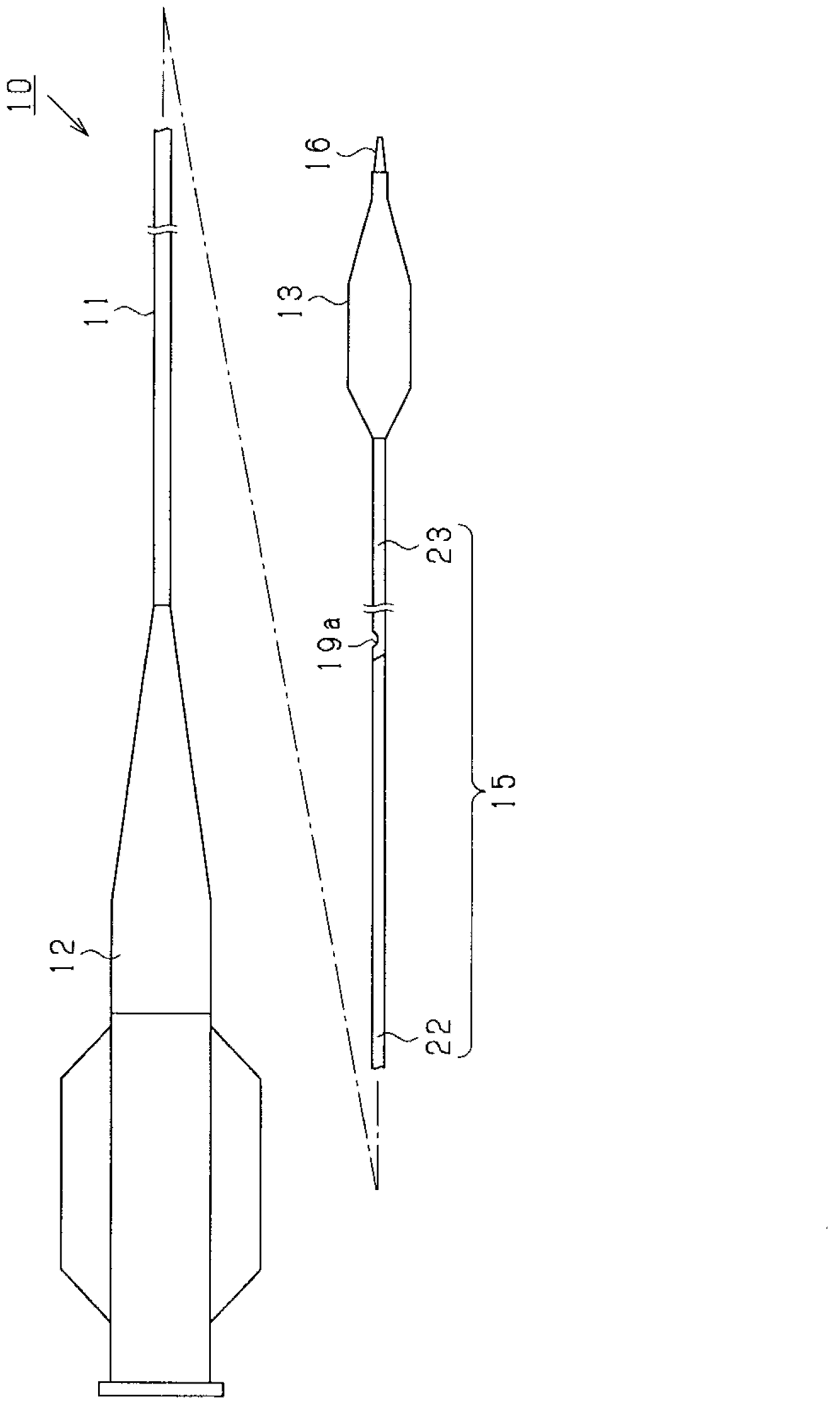
[0042] Hereinafter, an embodiment of a balloon catheter will be described with reference to the drawings. First, refer to figure 1 The brief structure of the balloon catheter 10 will be described. figure 1 It is a schematic overall side view showing the structure of the balloon catheter 10.

[0043] Such as figure 1 As shown, the balloon catheter 10 includes a catheter tube 11, a bush 12 attached to the proximal end (base end) of the catheter tube 11, and a balloon attached to the distal end (tip side) of the catheter tube 11. 13.

[0044] The catheter tube 11 is composed of a plurality of tubes, and has an inner-outer multi-tube structure from at least a midway position in the axial direction (longitudinal direction) to a position of the balloon 13. Specifically, the catheter pipe 11 includes an outer pipe 15 and an inner pipe 16 having a smaller inner diameter and outer diameter than the outer pipe 15, and the inner pipe 16 is inserted into the outer pipe 15 to form an inner ...

no. 2 approach 〕

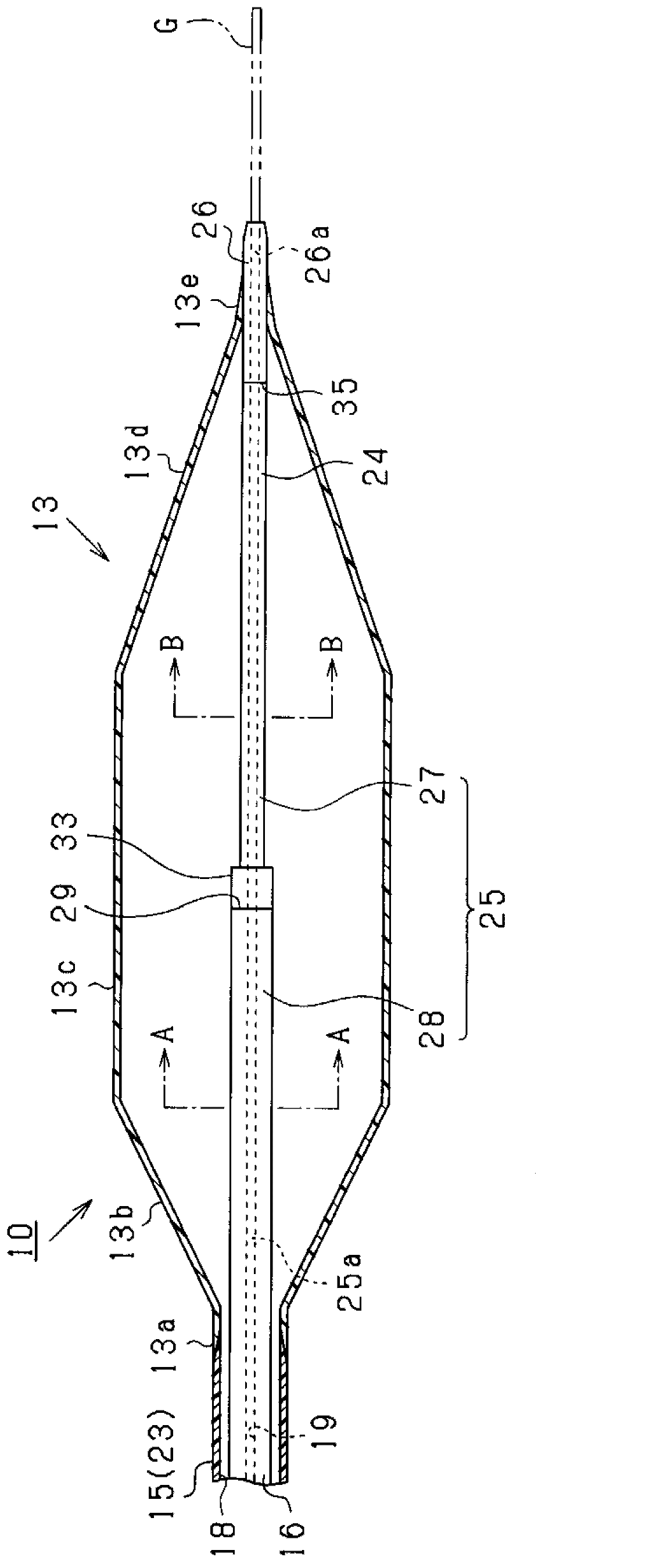
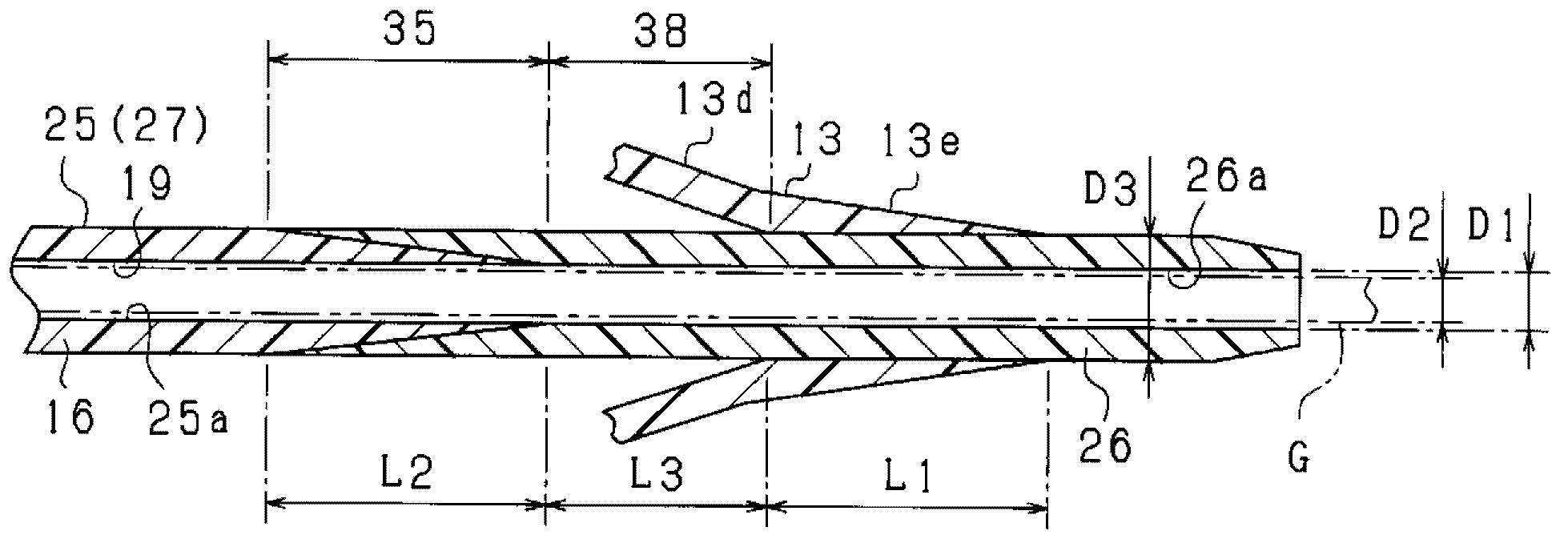
[0098] In this embodiment, the joining portion 35 of the inner tube 16 is joined to the distal side strut region 13e of the balloon 13, which is different from the structure of the first embodiment described above. Below, according to Figure 8 The structure of this embodiment will be described. It should be noted, Figure 8 It is a longitudinal cross-sectional view showing the junction between the inner tube 16 and the balloon 13.

[0099] Such as Figure 8 As shown, in the balloon catheter 40 of this embodiment, the joint 35 of the inner tube 16 is arranged at the same position in the axial direction as the distal strut region 13e of the balloon 13, and the joint 35 is thermally fused The compress is joined to the distal side pillar region 13e. Specifically, in this joined state, in the axial direction, the proximal end (base end) of the joining portion 35 is located closer to the proximal end (base end) than the proximal end of the distal side strut region 13e, The distal...


PUM


Abstract

The invention provides a balloon catheter capable of suppressing decrease in the passing capability of a guide wire. The balloon catheter comprises an inner pipeline (16) and a sacculus (13) covering the far end of the inner pipeline (16). A far end pillar area (13e) combined with the inner pipeline (16) is disposed on the far end portion of the sacculus (13). The inner pipeline (16) comprises a basic pipeline (25) and a tip pipeline (26), wherein the tip pipeline (26) is arranged at a position closer to the far end side than the basic pipeline (25) and is combined with the basic pipeline (25) and the rigidity of the tip pipeline (26) is less than that of the basic pipeline (25). The combined part (35) of the basic pipeline (25) and the tip pipeline (26) is at a position closer to a near end side than the far end pillar area (13e) in the axis direction. The length of non-combined area (38) of the tip pipeline (26) is set as 1 mm, wherein the non-combined area (38) is closer to the far end side than the combined part (35) and closer to the near end side than the far end pillar area (13e).

Description

Technical field [0001] The present invention relates to a balloon catheter used for introduction into a living body for dilation treatment of a stenosis or occlusion of a blood vessel. Background technique [0002] Conventionally, balloon catheters have been used for treatments such as PTA (percutaneous angiogenesis) and PTCA (percutaneous coronary angiogenesis). The balloon catheter is equipped with a catheter tube and a balloon provided on the distal end side of the catheter tube. The balloon is introduced into a site that is narrowed or occluded due to lesions in the blood vessel, etc., and expands it. Expansion of the site. [0003] In order to improve the flexibility of the distal end side of the balloon catheter, there is a case where a distal tip having overall flexibility is provided in a predetermined range from the distal end to the proximal side (for example, refer to Patent Document 1). Picture 9 Show one example. Picture 9 The illustrated balloon catheter 50 includes ...

Claims


Application Information

Patent Timeline
Patent Type & Authority Applications(China)
IPC IPC(8): A61M29/02A61M25/10
Inventor 中川裕树杉浦寿史岩野健志三宅孝政
Owner GOODMAN & COMPANY
Why Eureka
Try Eureka