Compressor, refrigerator and equipment
A technology for compressors and compression mechanisms, applied in compressors, refrigerators/freezers, household refrigerators, etc., can solve problems such as cost increase, reliability reduction, and demand, and achieve noise reduction, length shortening, and low cost. Effect
- Summary
- Abstract
- Description
- Claims
- Application Information
AI Technical Summary
Problems solved by technology
Method used
Image

Examples
Embodiment approach 1
[0048] (The mechanical room is arranged at the lower back of the main body of the refrigerator)
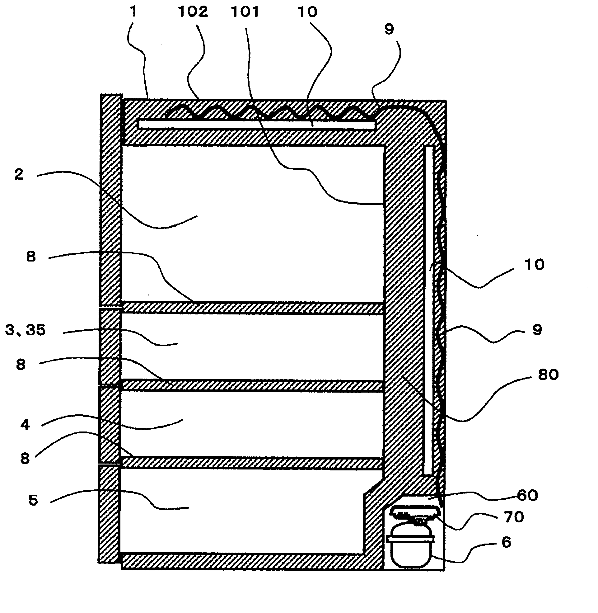
[0049] figure 1 It is a side sectional view of the refrigerator in Embodiment 1 of this invention seen from a side wall. In the figure, a refrigerating chamber 2 is provided on the uppermost section of the refrigerator main body 1, a switch chamber 3 and an ice making chamber 35 are arranged side by side under the refrigerating chamber 2, and a refrigerating chamber 3 and an ice making chamber 35 are arranged below the switching chamber 3 and the ice making chamber 35. As for the compartment 4, the vegetable compartment 5 is provided under the freezer compartment 4 (the lowermost stage). Here, among the storage rooms (for example, the refrigerator room 2, the switch room 3, the ice room 35, the freezer room 4, and the vegetable room 5), the rooms with different set temperatures (storage temperatures) are covered with heat insulating materials (yes). Partition parts, polyurethane...
PUM
 Abstract
Description
Claims
Application Information
 - Generate Ideas
- Intellectual Property
- Life Sciences
- Materials
- Tech Scout
- Unparalleled Data Quality
- Higher Quality Content
- 60% Fewer Hallucinations
Browse by: Latest US Patents, China's latest patents, Technical Efficacy Thesaurus, Application Domain, Technology Topic, Popular Technical Reports.
© 2025 PatSnap. All rights reserved.Legal|Privacy policy|Modern Slavery Act Transparency Statement|Sitemap|About US| Contact US: help@patsnap.com