Method for processing atmosphere plasma of large-diameter optical part

A technology for optical parts and plasma, applied in metal processing equipment, optical surface grinders, manufacturing tools, etc., can solve the problems of low processing efficiency, inability to meet the mass demand of large-diameter optical components, etc., to improve processing efficiency and improve processing. Accuracy and surface shape convergence speed, the effect of reducing the processing cost

Inactive Publication Date: 2013-08-07
HARBIN INST OF TECH
View PDF6 Cites 8 Cited by
  • Summary
  • Abstract
  • Description
  • Claims
  • Application Information

AI Technical Summary

Problems solved by technology

[0004] The purpose of the present invention is to provide an atmospheric plasma processing method for large-diameter optical parts, in order to solve the problem that the traditional mechanical polishing technology has low processing efficiency and cannot meet the large-scale demand for large-diameter optical components in the optical field

Method used


Image

  • Method for processing atmosphere plasma of large-diameter optical part

Examples


specific Embodiment approach 1

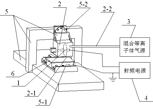
[0020] Specific implementation mode one: as figure 1 As shown, its steps are:

[0021] Step 1: Install the atmospheric plasma rotating electrode 1 in the sealed cover 2, and the lower end of the sealed cover 2 has an opening 2-1, so that the inner cavity of the sealed cover 2 is connected with the mixed plasma gas source 3 through the gas pipe 2-2, The atmospheric plasma rotating electrode 1 is connected to the output end of the radio frequency power supply 4 as the anode of the atmospheric plasma discharge;

[0022] Step 2: Insulate and connect the upper end of the sealing cover 2 to the vertical movement work platform 5-2 of the gantry processing machine tool 5, and mount and clamp the optical part 6 to be processed on the horizontal movement work platform 5-1 of the gantry processing machine tool 5; The working platform 5-1 of the gantry processing machine tool 5 is connected to the radio frequency power supply 4 and grounded as the cathode of the atmospheric plasma discha...


PUM


Abstract

The invention provides a method for processing atmosphere plasma of a large-diameter optical part and belongs to the field of optical processing. The problem in a traditional mechanical polishing technology that processing efficiency is low and requirements of the optical field for a large batch of large-diameter optical components can not be met. The method includes: step 1, arranging an atmosphere plasma rotating electrode in a sealing cover; step 2, connecting the upper end of the sealing cover with a working shaft in an isolation mode, and clamping an optical part to be processed on a working platform; step 3, enabling the atmosphere plasma rotating electrode to be close to a surface to be processed of the optical part to be processed; step 4, pre-heating a radio frequency power supply and opening a mixed plasma gas source; step 5, starting the radio frequency power supply; step 6, processing the surface of the part through the generated atmosphere plasma; and step 7, taking out the optical part to be processed. By means of the method, a discharging gap between the rotating electrode and the part to be processed is used for generating the plasma, the method is a non-contact chemical processing method, and an affected layer generated in machining is avoided.

Description

technical field [0001] The invention belongs to the field of optical processing. Background technique [0002] CCOS (Computer Controlled Optical Surfacing) is an optical processing technology developed in the 1970s. With the development of computer technology, CCOS technology has been further improved, which has greatly promoted the development of optical parts manufacturing technology, especially in the polishing process of large-diameter and high-precision aspheric surfaces, which reduces the requirements for operator experience and technology, and improves repeatability. . [0003] At present, the processing of large-caliber optical parts mainly adopts the polishing grinding head or the small tool polishing of the polishing head based on the principle of CCOS. The polishing process belongs to contact processing, which mainly relies on the mechanical action of fine abrasive grains to cause plastic deformation of the processing material to achieve removal processing. Ther...

Claims


Application Information

Patent Timeline
Patent Type & Authority Applications(China)
IPC IPC(8): B24B13/00
Inventor 王波金会良姚英学李娜车琳辛强金江李铎
Owner HARBIN INST OF TECH
Why Eureka
Try Eureka