Multistage pressure cylinder and pressurization usage method and depressurization usage method thereof

A technology of booster cylinder and secondary booster, applied in the field of hydraulic booster cylinder, can solve the problems of low utilization rate of energy recovery, difficult to control the pressurization process, waste of energy, etc. consumption effect

Active Publication Date: 2013-08-07
FUJIAN HAIYUAN AUTOMATIC EQUIP CO LTD
View PDF9 Cites 5 Cited by
  • Summary
  • Abstract
  • Description
  • Claims
  • Application Information

AI Technical Summary

Problems solved by technology

[0003] The system pressure oil of the hydraulic press is generally 15-17MPa, and the maximum pressure can reach 30-35MPa after boosting. Since the main hydraulic cylinder of the hydraulic press has a large volume, the pressurization of the main hydraulic cylinder from the system pressure to the boost pressure is a gradual increase in pressure. In the initial stage of supercharging, the pressure difference between the pressure of the main hydraulic cylinder and the working pressure of the supercharging cylinder is close to 20MPa. Can be converted into heat or noise, wasting energy
[0004] After the pressing is completed, the main hydraulic cylinder stores a considerable amount of hydraulic energy. The general method of pressure relief and recovery of pressure energy is to directly release the high-pressure oil in the upper chamber of the main hydraulic cylinder to the accumulator group. However, due to the large pressure difference, there is Hydraulic shock, have to use accumulators with high pressure resistance, and the energy recovery rate is low

Method used


Image

  • Multistage pressure cylinder and pressurization usage method and depressurization usage method thereof
  • Multistage pressure cylinder and pressurization usage method and depressurization usage method thereof
  • Multistage pressure cylinder and pressurization usage method and depressurization usage method thereof

Examples


Embodiment Construction

[0038] Best practice:

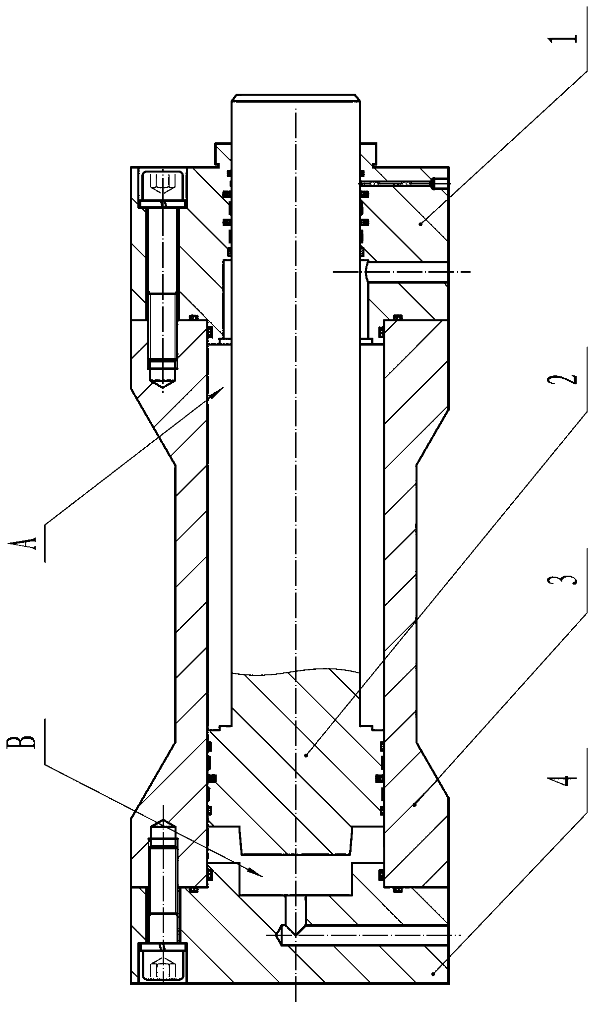
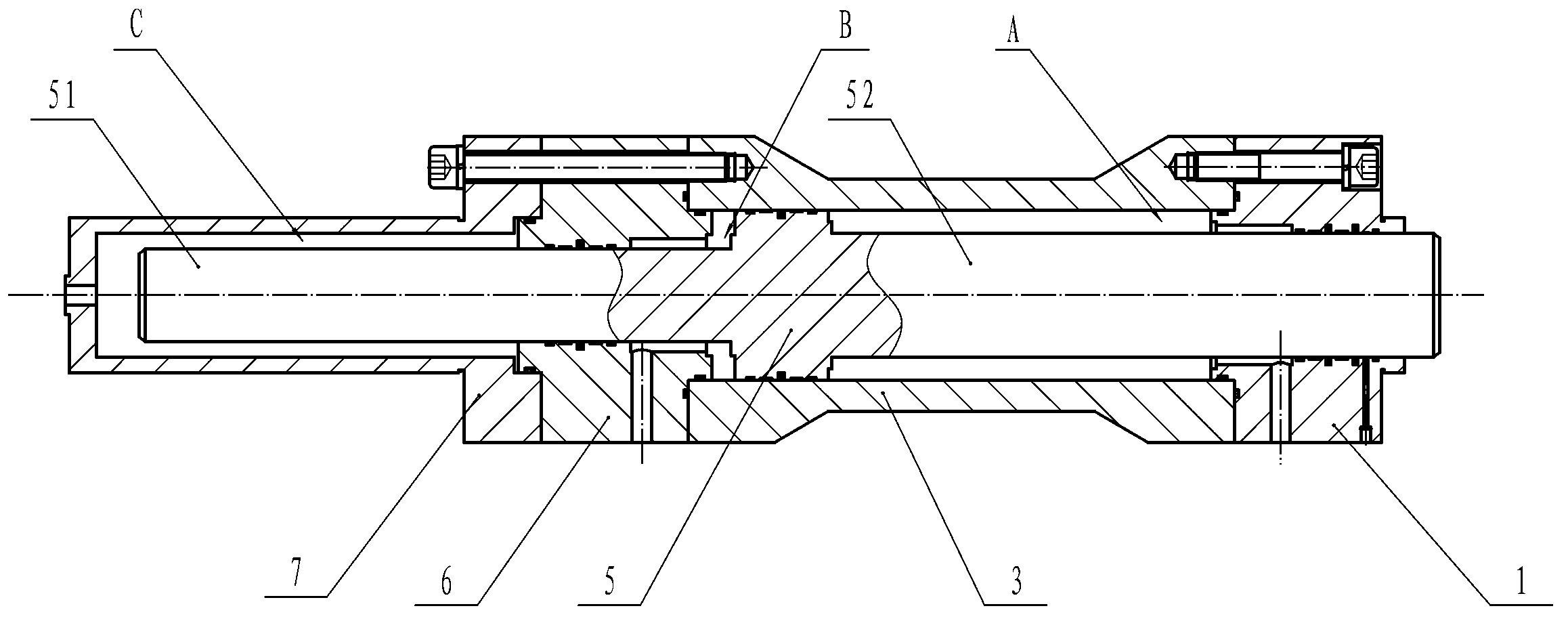
[0039] Such as figure 2 As shown, the multi-stage booster cylinder includes a front cylinder cover 1, a cylinder barrel 3, a piston 2 and a rear cylinder cover 4, the piston 2, the piston front rod 51 and the front cylinder cover 1 form an A cavity with a front rod, and also includes The secondary booster cylinder 7, the piston has a rear rod, the secondary booster cylinder 7 is fixedly installed behind the rear cylinder head 4, and the piston rear rod 51 passes through the rear cylinder head 4 and enters the rear of the secondary booster cylinder 7. In the barrel cavity, the piston rear rod 51, the cylinder barrel 3, and the rear cylinder cover 4 form the B chamber with the rear rod, and the rear cylinder cover 4, the piston rear rod 51, and the secondary booster cylinder 7 form the C cavity with the rear rod. The effective area of ​​chamber B is larger than that of chamber A, and the effective area of ​​chamber C is smaller than that of chamber A. T...


PUM


Abstract

The invention relates to a multistage pressure cylinder. According to the multistage pressure cylinder, an ordinary pressure cylinder cavity B is divided into a cavity body B and a cavity body C through adding of a back rod of a piston and a secondary pressure cylinder, multiple pressure ratios which are convertible are provided, one of the cavity body B and the cavity body C, which is provided with the larger effective area, serves as a cavity body D, and the other one of the cavity body B and the cavity body C, which is provided with the smaller effective area, serves as a cavity body E. The pressurization process comprises two steps, firstly, pressure oil is input into the cavity body D, and a cavity body A outputs hydraulic oil with the pressure ratio to be D / A (an area ratio); and then the pressure oil is input into the cavity body D and the cavity body E simultaneously, and the cavity body A outputs the hydraulic oil with the pressure ratio to be (D+E) / A (an area ratio) to complete the pressurization process. During depressurization, firstly, a main hydraulic cylinder is communicated with the cavity body A of the multistage pressure cylinder, the cavity body D is communicated with an energy accumulator group, a liquid is charged into the energy accumulator group after the depressurization with the pressure reducing ratio of A / D (an area ratio) is achieved, and then the depressurization is conducted step by step. The multistage pressure cylinder is used in a hydraulic system of a hydraulic machine to achieve graded pressurization during pressurization, graded energy recovery is achieved stably through conversion of pressure ratios during depressurization, and hydraulic shocks are reduced.

Description

technical field [0001] The invention relates to a hydraulic booster cylinder, in particular to a multi-stage booster cylinder and its pressurization and pressure release methods. Background technique [0002] In order to improve the efficiency of pressing and reduce the pressure level of hydraulic system pipelines and valves during the pressing process of hydraulic presses, booster cylinders are usually used, such as figure 1 The typical structure of the booster cylinder is composed of front cylinder head 1, piston 2, cylinder barrel 3 and rear cylinder head 4. 3. The rear cylinder head 4 forms a rodless chamber B. The effective area of ​​cavity A is smaller than that of cavity B, and the effective area ratio is usually about 1:2.0-2.5. During pressurization, under the control of the hydraulic system, the system pressure oil is input into chamber B, and the hydraulic oil in chamber A boosted by the effective area ratio is output to the main hydraulic cylinder of the hydrau...

Claims


Application Information

Patent Timeline
Patent Type & Authority Applications(China)
IPC IPC(8): F15B15/22F15B21/14F15B15/14
Inventor 林项武王琳
Owner FUJIAN HAIYUAN AUTOMATIC EQUIP CO LTD
Why Eureka
Try Eureka