Furnace type efficient recovery system for flue gas waste heat of cooled sinter

A sinter and waste heat technology, which is applied in the direction of improving energy efficiency, furnace, waste heat treatment, etc., can solve the problems of large heat exchange end difference between sinter and cooling air, large influence of waste heat utilization, large fluctuation of waste heat parameters, etc., to achieve improvement System adaptability and safety, improving waste heat utilization efficiency, and reducing system power consumption

Inactive Publication Date: 2013-08-07
CITIC HEAVY INDUSTRIES CO LTD +1
View PDF6 Cites 6 Cited by
  • Summary
  • Abstract
  • Description
  • Claims
  • Application Information

AI Technical Summary

Problems solved by technology

[0007] 1. Insufficient heat exchange
Cross-flow heat exchange between sinter and cooling air in belt cooler or ring cooler, the heat transfer effect is poor; the accumulation height of sinter material layer is low, the heat exchange time between hot sinter and cooling air is short, and the heat exchange is insufficient
[0008] 2. Poor sealing and serious air leakage
The quality of the sealing effect directly determines the performance and power generation of the power generation system. Limited by the structure of the belt cooler or the ring cooler, the seal of the belt cooler or the ring cooler is poor, and the air leakage is serious
[0009] 3. Low utilization efficiency of waste heat
In the existing sintering machine waste heat power generation system, the air is generally taken from the higher temperature sections I and II of the belt cooler or ring cooler. The heat exchange end difference between the sintered ore and the cooling air is large

Method used


Image

  • Furnace type efficient recovery system for flue gas waste heat of cooled sinter

Examples


Example Embodiment

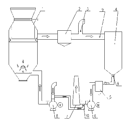
[0027] The present invention will be further described below in conjunction with the description of the drawings and the specific embodiments. Such as figure 1 As shown, a furnace-type cooling sinter waste heat and high-efficiency recovery flue gas system includes a cooling furnace 1, a primary dust collector 2, an emergency release valve 3, a waste heat boiler 4, a secondary dust collector 5, an induced draft fan 6, a chimney 7 and a blower 8. The upper flue gas outlet of the cooling furnace 1 is connected to the primary dust collector 2, the waste heat boiler 4, the secondary dust collector 5, the induced draft fan 6 and the blower 8 through the pipeline. The air outlet of the blower 8 is connected to the lower cooling gas inlet of the cooling furnace 1. , The pipe between the primary dust collector 2 and the waste heat boiler 4 is provided with an emergency relief valve 3, and the pipe between the induced draft fan 6 and the blower 8 is provided with a chimney 7. The waste ...


PUM


Abstract

A furnace type efficient recovery system for flue gas waste heat of cooled sinter comprises an air blower, a cooling furnace, a primary dust remover, an emergency blow-off valve, a waste heat boiler, a secondary dust remover, a draft fan and a chimney. An outlet of the air blower is communicated with a cooling air inlet on the lower portion of the cooling furnace. A flue gas outlet on the upper portion of the cooling furnace is communicated with the primary dust remover, the waste heat boiler, the secondary dust remover, the draft fan and the chimney through pipelines successively. The emergency blow-off valve is arranged on a pipeline between the primary dust remover and the waste heat boiler. A connection pipeline is arranged between the draft fan and the air blower. The furnace type efficient recovery system for flue gas waste heat of cooled sinter has the advantages that the sinter quality is improved, the sinter return rate is reduced, flue gas parameters are stable, the system own power consumption rate is reduced, and the energy-saving effect is apparent.

Description

technical field [0001] The invention belongs to the technical field of waste heat power generation, and in particular relates to a system for efficiently recovering flue gas from furnace-type cooling sinter waste heat. Background technique [0002] The iron and steel industry is an important basic industry of the national economy, and its energy consumption accounts for about 15% of the total industrial energy consumption in the country. It is a key industry for energy conservation and emission reduction. In the process of iron and steel production, the energy consumption of the sintering process is relatively high, generally accounting for 10-12% of the total energy consumption of iron and steel enterprises, second only to the ironmaking process, and has a huge potential for energy saving. In the sintering process, the hot sintered ore discharged from the sintering machine must be cooled to about 150°C before entering the next process. At present, the sinter is cooled by u...

Claims


Application Information

Patent Timeline
IPC IPC(8): F27D17/00
CPCY02P10/25
Inventor 王继生彭岩仝伟峰王新建范东燕时小宝张晗
Owner CITIC HEAVY INDUSTRIES CO LTD
Why Eureka
Try Eureka