Image despinning device capable of being applied to slit type grid spectrometer of solar telescope

A technology for solar telescopes and grating spectrometers, applied in the field of image derotation devices, can solve the problems of strict electrical and mechanical control, limited optical adjustment, etc., and achieve the effects of eliminating image rotation, improving flexibility, and simple derotation structure

Active Publication Date: 2013-08-07
INST OF OPTICS & ELECTRONICS - CHINESE ACAD OF SCI
View PDF3 Cites 6 Cited by
  • Summary
  • Abstract
  • Description
  • Claims
  • Application Information

AI Technical Summary

Problems solved by technology

[0005] The technical problem to be solved by the present invention is: Aiming at the problems that traditional image derotation techniques such as optical derotation and mechanical derotation technology are limited by optical adjustment, electrical contr

Method used


Image

  • Image despinning device capable of being applied to slit type grid spectrometer of solar telescope
  • Image despinning device capable of being applied to slit type grid spectrometer of solar telescope
  • Image despinning device capable of being applied to slit type grid spectrometer of solar telescope

Examples


Embodiment Construction

[0027] The present invention will be further described below in conjunction with examples.

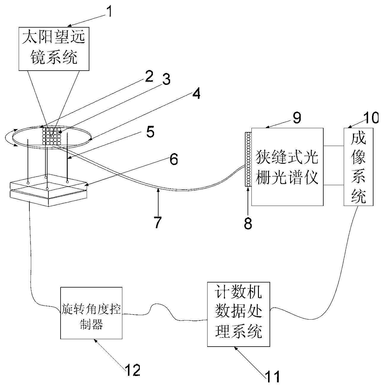
[0028] Such as figure 1 As shown, an image derotation device that can be used for a solar telescope slit grating spectrometer includes: a solar telescope system 1, a fiber holder slot 2, an area array fiber holder end 3, a support disc 4, a rigid connector 5, Electric rotating table 6, optical fiber bundle 7, linear array optical fiber clamp end 8, slit grating spectrometer 9, imaging system 10, computer data processing system 11 and rotation angle controller 12. The solar telescope system 1 is a ground-based large-aperture solar telescope.

[0029] The ground-based large-aperture solar telescope images the solar image on the focal plane of the ground-based large-aperture solar telescope. However, since the ground-based large-aperture solar telescope generally adopts a horizontal rack structure, when tracking the sun for observation, the horizon longitude where the telescope is locate...


PUM


Abstract

The invention provides an image despinning device capable of being applied to a slit type grid spectrometer of a solar telescope. The device comprises a solar telescope system (1), an optical fiber clamp slot (2), an area array optical fiber clamp end (3), a support circular disc (4), a rigid connecting body (5), a power-driven rotation platform (6), an optical fiber beam (7), a linear array optical fiber clamp end (8), the slit type grid spectrometer (9), an imaging system (10), a computer data processing system (11) and a rotary angle controller (12), wherein a telescope focal surface is connected with the slit type grid spectrometer in the rear end through the optical fiber beam, according to the principle of simple optical fiber beam flexible image transmitting, relay is carried out on a solar image which enters into the slit type spectrometer, and conversion of the scope of the solar image via flexible rotation is realized. The device is small in structure, light in weight, simple in use and flexible in structure, so that the separation of the telescope system from the spectrometer on a space can be realized, and the position and the placing range of the spectrometer are not limited.

Description

technical field [0001] The invention relates to an image derotation device of a solar telescope slit type solar grating spectrometer. Background technique [0002] The ground-based large-aperture solar telescopes all adopt a horizontal frame structure, so when tracking the sun for observation, it is necessary to rotate the telescope's azimuth axis and the coordinated linkage of the pitch axis, because the telescope's azimuth axis and pitch axis are not in line with the earth's rotation The axes are parallel, so when the telescope tracks the sun for observation, there will be an image rotation problem on the solar image on the focal plane of the telescope (Cheng Jingquan. Principles and Design of Astronomical Telescopes [M]. Beijing: China Science and Technology Press, 2003: 95 -96.). The image rotation will bring serious problems to real-time target recognition, image processing and the work of back-end scientific instruments such as spectrometers, so the image rotation pro...

Claims


Application Information

Patent Timeline
IPC IPC(8): G01J3/02G01J3/28
Inventor 郑联慧顾乃庭饶长辉
Owner INST OF OPTICS & ELECTRONICS - CHINESE ACAD OF SCI
Why Eureka
Try Eureka