

Pressure sensor micro-nano structure with high stability under high-temperature environment
A pressure sensor, high stability technology, applied in the field of pressure sensor micro-nano structure, can solve problems such as current leakage, signal processing system and circuit imbalance, failure, etc., achieve low temperature drift, strong anti-interference ability, simple structure effect
- Summary
- Abstract
- Description
- Claims
- Application Information
AI Technical Summary
Problems solved by technology
Method used
Image

Examples
Embodiment Construction
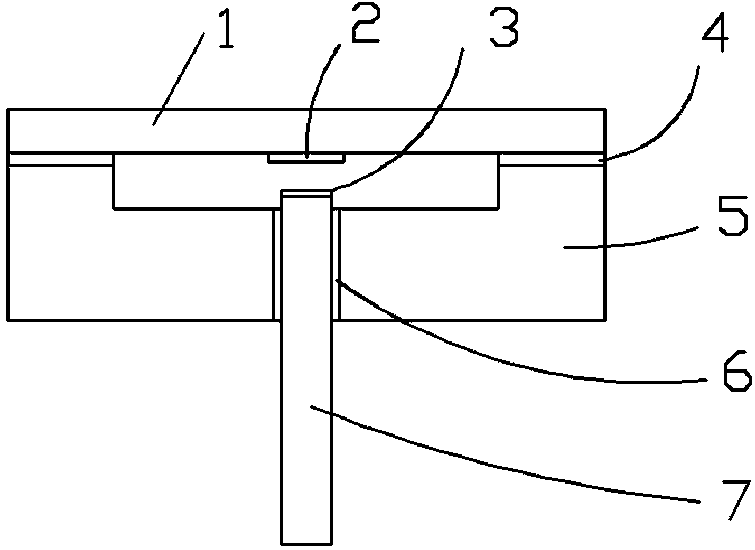
[0027] see figure 1 , the present invention is a pressure sensor micro-nano structure with high stability under high temperature environment, which includes: silicon carbide diaphragm 1, reflective film 2, semi-reflective film 3, bonding layer 4, silicon carbide substrate 5, encapsulation layer 6 and sapphire optical fiber 7; the positional connection relationship between them is: the reflective film 2 is coated on the middle part of the silicon carbide diaphragm 1, the semi-reflective film 3 is coated on the end of the sapphire optical fiber 7, and the bonding layer 4 is located between the silicon carbide diaphragm 1 and the carbonized Between the silicon substrates 5 , the sapphire optical fiber 7 is connected to the silicon carbide substrate 5 through the encapsulation layer 6 for transmitting optical signals.
[0028] The silicon carbide diaphragm 1 is a circular sheet, which will cause deformation of the diaphragm when a pressure is applied from the outside to sense the ...
PUM
| Property | Measurement | Unit |
|---|---|---|
| Thickness | aaaaa | aaaaa |
| Diameter | aaaaa | aaaaa |
| Thickness | aaaaa | aaaaa |
Abstract
Description
Claims
Application Information