Shaping method for experimental grotto of earthquake simulated vibration platform model

A technology of model testing and forming methods, applied in vibration testing, testing of machine/structural components, measuring devices, etc., can solve problems such as inability to use models to form, and achieve the effect of simple manufacturing process

Inactive Publication Date: 2013-08-07
INST OF ROCK AND SOIL MECHANICS - CHINESE ACAD OF SCI
View PDF10 Cites 6 Cited by
  • Summary
  • Abstract
  • Description
  • Claims
  • Application Information

AI Technical Summary

Problems solved by technology

[0004] 1. Chinese Patent Publication No. CN102691511A, publication date 2012.9.26, the title of the invention is "Cavity Forming Device for Buried Cavern in Underground Engineering Test Model", this application introduces a cavity forming device for buried cavern in underground engineering test model device, which is mainly used for the molding of ellipsoidal cavity structures, and cannot be used for the molding of long cavern models such as underground powerhouses of hydropower stations and traffic tunnels
[0005] 2. Chinese Patent Publication No. CN102444410A, the publication date is May 9, 2012, and the title of the invention is "Positioning and Forming Method for Geomechanical Model Test Buried Cavities". This application introduces the positioning of a buried cavern for geomechanical model tests And forming method, this method is mainly used for the positioning and forming of ellipsoidal cavity structure, and also cannot be used for forming long cavity models such as underground powerhouses of hydropower stations and traffic tunnels

Method used


Image

  • Shaping method for experimental grotto of earthquake simulated vibration platform model
  • Shaping method for experimental grotto of earthquake simulated vibration platform model
  • Shaping method for experimental grotto of earthquake simulated vibration platform model

Examples


Embodiment Construction

[0029] Below in conjunction with accompanying drawing, the present invention is described in further detail:

[0030] A method for forming an earthquake simulation shaking table model test cavity, comprising the following steps:

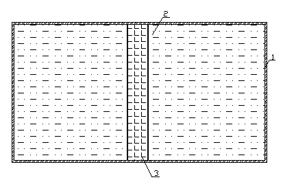
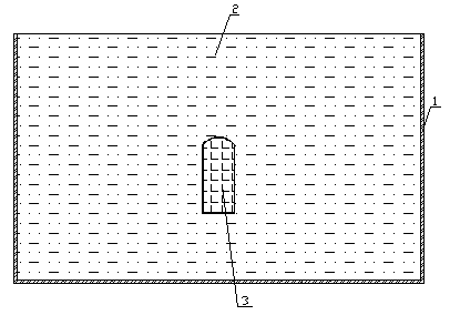
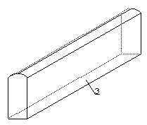
[0031] 1 Make the cavern solid model: Calculate the size of the cavern model in the model test according to the size of the real cavern in the actual project and the geometric similarity scale, and make a wooden mold with the same shape according to the calculated size of the cavern model, such as image 3 As shown, the molding density according to the mold size is 22Kg / m 3 The hardened and weighted polystyrene foam cavity model, remove the wooden mold after molding, and wrap a layer of polyvinyl chloride plastic with a thickness of 1mm on the surface of the model;

[0032] 2 Locate the cavern entity model: According to the position of the cavern model in the test design plan, use a ruler to determine the reserved position of the cavern on the inner...


PUM


Abstract

The invention relates to a shaping method for an experimental grotto of an earthquake simulated vibration platform model. The method comprises the following steps of 1), manufacturing a wood mould with a grotto size consistent to an experimental request of a model, molding, additionally hardening and weighing a polystyrene foaming grotto model according to a model size, and wrapping a layer of polyvinyl chloride plastics on the surface of the grotto model; 2), drawing a grotto profile on a side wall in a model box according to a designed position for positioning, and fixing the borders of the grotto and the model box by the adoption of square wooden strips; 3), stuffing and symmetrically ramming around the grotto, and enabling the grotto model not to generate deviation; and 4), firstly digging the middle part of a grotto cross section, and then digging the edge and corner parts by utilizing the protection of plastic cloth on the outer layer of the model. By the adoption of the method, grottos with different shapes and sizes can be high-efficiently, simply and conveniently manufactured in model experiments, the accurate positioning of a grotto space is realized, the digging method is simple and convenient, and interference with model materials surrounding the grotto during the digging process is effectively reduced.

Description

technical field [0001] The invention relates to a method for forming a cavity for an earthquake simulation shaking table model test, and mainly relates to a method for forming a cavity for an earthquake simulation shaking table model test in engineering fields such as hydropower, transportation and energy. Background technique [0002] With the rapid development of hydropower, transportation and underground resource project construction, underground cavern structures have been widely used in these fields. At the same time, the stability of underground cavern structures under earthquakes has also received more and more attention and attention. Due to the characteristics of large-scale engineering and complex geological conditions in most underground projects, the stability analysis and evaluation of underground cavern structures need to rely on model experiments in addition to theoretical research and numerical calculation methods. Model test is an early-developed, widely us...

Claims


Application Information

Patent Timeline
Patent Type & Authority Applications(China)
IPC IPC(8): G01M7/02
Inventor 盛谦陈健刘晓敏冷先伦朱泽奇张勇慧陈国良
Owner INST OF ROCK AND SOIL MECHANICS - CHINESE ACAD OF SCI
Why Eureka
Try Eureka