High-power non-contact type rapid laser heating device

A non-contact, rapid heating technology, applied in the preparation of test samples, etc., can solve the problems of low heating rate, thermal shock, ablation test, high construction and operation costs, and achieve low cost and linearly adjustable output power Effect

Active Publication Date: 2013-08-07
HARBIN INST OF TECH
View PDF6 Cites 24 Cited by
  • Summary
  • Abstract
  • Description
  • Claims
  • Application Information

AI Technical Summary

Problems solved by technology

Typical ones are high-vacuum flat graphite heating furnace, quartz lamp array photoelectric heating furnace and solar radiation heating device. This heating method can realize static heating of all materials, but the heat flux generated is low and the heating rate is low, so it cannot be effectively The thermal shock, ablation and other performance tests have great limitations; the pneumatic heating devices mainly include arc wind tunnels, high-frequency plasma wind tunnels, and oxyacetylene, which can generate stable flow fields with high heat flux density for testing And evaluate the ablation, thermal shock, temperature resistance, sealing and other properties of anti / heat insulation materials. However, this kind of equipment system has complex structure, high construction and operation costs, and difficult adjustment and calibration of heat flow parameters. High, high requirements for supporting facilities, low safety and controllability, especially the impurities in the flow field will chemically react with the material, thus affecting the test effect

Method used


Image

  • High-power non-contact type rapid laser heating device
  • High-power non-contact type rapid laser heating device

Examples


Embodiment 1

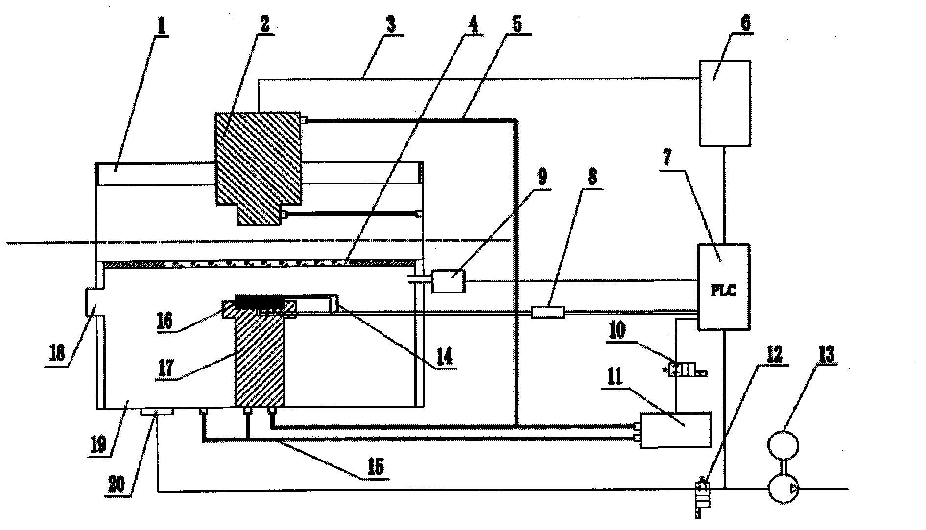
[0024] This embodiment is a high-power non-contact laser rapid heating device, including a semiconductor laser 6, the laser energy is coupled into the optical fiber 3, the output end of the optical fiber 3 is connected to the lens 2, and the lens 2 is fixed on the adjustment bracket 1, by changing the bracket 1 The position and the focal length of the lens 2 adjust the heating area, the laser beam passes through the optical fiber 3 and the lens 2, and converges on the sample 16 through the CaF2 window above the environmental chamber 19, and the sample is placed on the water-cooling bracket 17, and the first cooling circulating water pipe 5 are respectively connected to the lens 2, the water-cooling bracket 17 and the refrigerator 11, and the second cold water circulation pipe 15 is respectively connected to the water-cooling bracket 17, the environmental chamber 19 and the refrigerator 11, and is controlled by the PLC control subsystem 7, and the thermocouple probe 14 is placed...

Embodiment 2

[0028] This embodiment is a high-power non-contact laser rapid heating device, including a semiconductor laser 6, the laser energy is coupled into the optical fiber 3, the output end of the optical fiber 3 is connected to the lens 2, and the lens 2 is fixed on the adjustment bracket 1, by changing the bracket 1 The position and the focal length of the lens 2 adjust the heating area, the laser beam passes through the optical fiber 3 and the lens 2, and converges on the sample 16 through the CaF2 window above the environmental chamber 19, and the sample is placed on the water-cooling bracket 17, and the first cooling circulating water pipe 5 are respectively connected to the lens 2, the water-cooling bracket 17 and the refrigerator 11, and the second cold water circulation pipe 15 is respectively connected to the water-cooling bracket 17, the environmental chamber 19 and the refrigerator 11, and is controlled by the PLC control subsystem 7, and the thermocouple probe 14 is placed...


PUM


Abstract

The invention provides a high-power non-contact type rapid laser heating device which comprises an adjustment bracket, a camera lens, an optical fiber, a CaF2 window, a first cooling circulating water pipe, a semiconductor laser, a programmable logic controller (PLC) subsystem, a thermoelectric couple temperature sensor, a resistance vacuum gauge, an electromagnetic valve, a refrigerator, a vacuum solenoid valve, a vacuum pump, a thermocouple probe, a second cooling circulating water pipe, a sample, a water-cooling bracket, an air inlet valve, an environmental chamber and a vacuum flange. The rapid laser heating device is in non-contact type, adjustable in output power linearity and low in cost. The high-power semiconductor laser enters the optical fiber by coupling and then generates high heating flux load by a converging combination lens, and heat prevention/insulation material in the environmental chamber can be heated, so that the service performances such as thermal shock, oxidation, ablation and the like can be tested.

Description

technical field [0001] The invention relates to a fiber-coupled semiconductor laser heating device, in particular to a high-power non-contact laser rapid heating device. Background technique [0002] The continuous development of aerospace technology has made hypersonic vehicles the focus of development in various countries at this stage, thus putting forward stringent requirements for the performance of thermal resistance limit, ablation, thermal shock and other performance of anti / heat insulation materials in high temperature environments. And test the performance of new anti / heat insulation materials, and establish a series of ground testing equipment. [0003] At present, the ground heating methods for testing the thermal shock, oxidation and service performance of anti / heat insulation materials are mainly divided into pneumatic heating, radiation heating, electric heating and induction heating. Since energized heating and induction heating require that the test materia...

Claims


Application Information

Patent Timeline
Patent Type & Authority Applications(China)
IPC IPC(8): G01N1/44
Inventor 孟松鹤金华徐凯许承海解维华
Owner HARBIN INST OF TECH
Why Eureka
Try Eureka