

PWM (pulse-width modulation) module capable of alternatively generating interruption mode and critical mode in flyback topology
A critical mode, flyback topology technology, used in output power conversion devices, DC power input to DC power output, instruments, etc. Circuit topology, breakdown and damage of switch tubes, etc., to achieve the effect of simple structure, less high-order harmonics, and low switching loss
Active Publication Date: 2013-08-07
顾选祥
View PDF8 Cites 7 Cited by
- Summary
- Abstract
- Description
- Claims
- Application Information
AI Technical Summary
Problems solved by technology
[0008] At present, the critical mode quasi-resonant PWM control chip (also known as the PWM control circuit with zero current detection on and peak current off) used in the switching power supply industry is mostly used in the BOOST topology without isolation as a PFC boost circuit, and rarely It is used in the flyback circuit topology with an isolation transformer. The reason is that under the condition of an isolation transformer, the reverse voltage across the drain-source (hereinafter referred to as D-S) of the switching tube will be 4-5 times higher than the input voltage, for example When the input voltage is 264V, the moment the switch tube is turned off, the reverse voltage generated at both ends of the MOS switch tube D-S can be as high as 1300V, which can easily cause the switch tube to be broken down and damaged (moreover, the current MOS switch tubes on the market are usually resistant The reverse voltage is below 1000V), which limits the application range of the critical mode quasi-resonant PWM control chip
Method used
View moreImage
Smart ImageViewing Examples

Examples
Embodiment Construction
[0027] The present invention will be further described below in conjunction with the accompanying drawings and embodiments.
Login to View More PUM
 Abstract
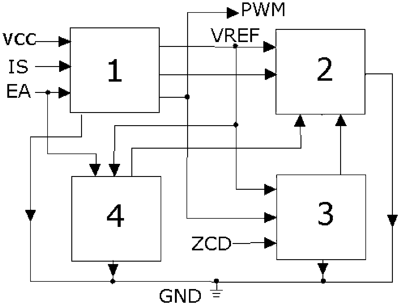
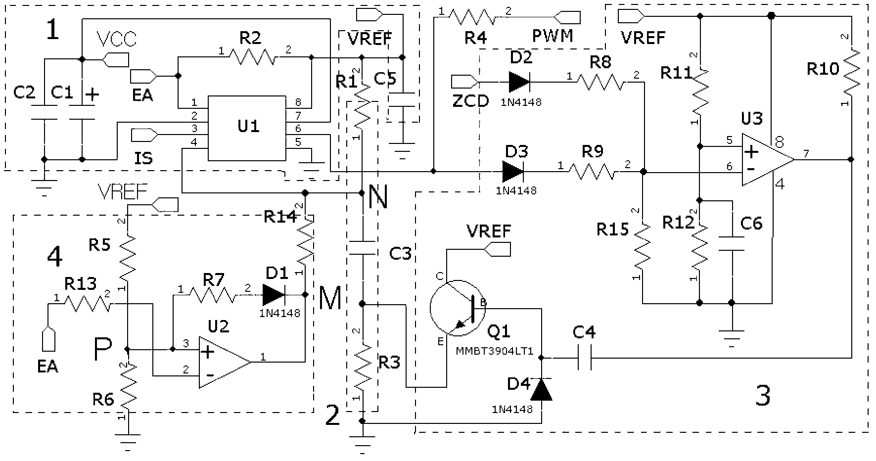
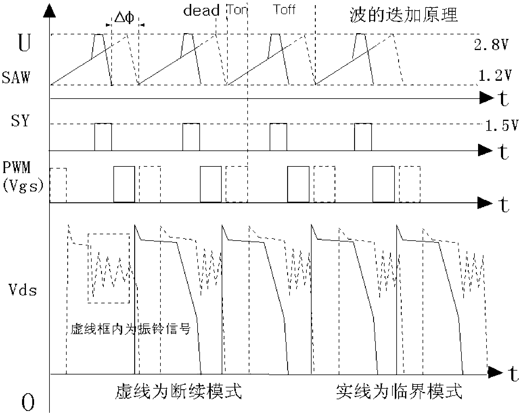
The invention discloses a PWM (pulse-width modulation) module which is applied to a flyback type switching power supply topology, can cause reverse voltage of D-S two ends of the topology to be lower and can always alternatively generate an interruption mode and a critical mode. The PWM module comprises a PWM control circuit and a sawtooth generator, and further comprises a zero current detection and start synchronizing circuit and a load weight sawtooth wave frequency conversion circuit, wherein the PWM control circuit is used for switching off fixed clock start peak current; the zero current detection and start synchronizing circuit can generate phase coherent waves; after the coherent waves and sawtooth waves are iterated, the PWM control circuit can start another alternative PWM signal output; and when a flyback circuit works in a current continuous mode, the sawtooth waves work under different frequencies by the load weight sawtooth wave frequency conversion circuit. According to the PWM module disclosed by the invention, the flyback circuit always works in a current interruption mode and critical mode alternatively generating state; the reverse voltage generated by the D-S two ends of a switching tube is reduced to 1.2-1.5 times of power source voltage; and the PWM module has a simple structure, the controlled flyback topology switching on-off loss is small, the service life is long and a few of ultraharmonics are generated.
Description
technical field [0001] The invention relates to a PWM control circuit for a switching power supply, in particular to a PWM control module for making a flyback topology circuit always in soft conduction. Background technique [0002] Flyback circuit topologies such as Figure 4 As shown, T1 is a high-frequency isolation transformer, Q1 is a switch tube, and D2 is a secondary side rectifier tube. During the conduction period of the switch tube (hereinafter referred to as Ton), the input voltage is applied to both ends of the primary coil. At this time, the voltage of the primary coil It is up positive and down negative, the voltage of the induction secondary coil is up negative and down positive, because D2 reverse cut-off, no energy is transmitted to the secondary, the magnetic field strength begins to increase gradually, and the electric energy is stored in the primary coil of the transformer in the form of magnetic energy. When the excitation current is equal to the magnitu...
Claims
Login to View More Application Information
Patent Timeline
 IPC IPC(8): H02M1/08H02M3/335
Inventor罗晓光
Owner顾选祥