Duplex piston ring-cylinder sleeve frictional wear test station

A friction and wear test, piston ring technology, applied in the direction of testing wear resistance, measuring devices, instruments, etc., can solve the problems of complex loading device, complex installation and manufacturing, and complex manufacturing, so as to improve test performance, save installation space, improve efficiency effect

Inactive Publication Date: 2013-08-14
HEFEI UNIV OF TECH
View PDF8 Cites 16 Cited by
  • Summary
  • Abstract
  • Description
  • Claims
  • Application Information

AI Technical Summary

Problems solved by technology

Among them, the test parameters of the sample test method are easier to control, and the repeatability and stability are relatively good, but they are quite different from the actual situation of the piston ring-cylinder liner, and the simulation is poor; the bench test method uses a simulated load for the ignition test. The controllability of the conditions is good, and the simulation of the actual working conditions of the engine is good, but the test period is long and the cost is high; while the component simulation test method is a method between the sample test and the bench test, and the actual The working conditions have better simulation, and have the advantages of shortening the test period, reducing the test cost, and improving the controllability of the test parameters, but the test efficiency and the size range of the test piece can also be further improved
The patent application number is: 200510136811.5, which discloses a method and equipment for friction and wear testing of cylinder liner and piston ring parts. It uses a mechanical radial load application method and equipment for friction and wear testing of cylinder liner and piston ring parts. The loading device is complicated. , the scope of application is limited
The patent application number is: 200710066372.4, which discloses a reciprocating piston ring-cylinder liner friction and wear testing machine, which uses a motor to drive the connecting rod mechanism, and converts it into a linear reciprocating motion through the slider and guide sleeve of the guiding mechanism. The installation is complicated and the cost is high. ; The patent application number is: 200820237523.8 discloses a piston ring-cylinder liner friction and wear tester, which uses a piston ring radial loading device composed of a loading nut, a screw rod, an inner tapered sleeve and an outer tapered sleeve to radially load the piston ring and Measure the strain of the screw rod with strain gauges to monitor the applied load in real time, but only test the small piston ring-cylinder liner as a whole; the patent application number is: 201110041655. In the test device, a crank-link mechanism is used to make the piston ring reciprocate between the cylinder liners, which is complex to manufacture and poor in balance, and only provides a test method for the piston ring-cylinder liner interception test piece; Sheng Yongshi (2012, Dalian Maritime University, master's thesis) designed the internal combustion engine cylinder liner-piston ring dual friction and wear test machine, using the dual mechanism and the complete cylinder liner-piston ring as the friction and wear sample to realize the friction and wear test of the two-cylinder internal combustion engine, But its test sample is relatively simple

Method used


Image

  • Duplex piston ring-cylinder sleeve frictional wear test station
  • Duplex piston ring-cylinder sleeve frictional wear test station
  • Duplex piston ring-cylinder sleeve frictional wear test station

Examples


Embodiment Construction

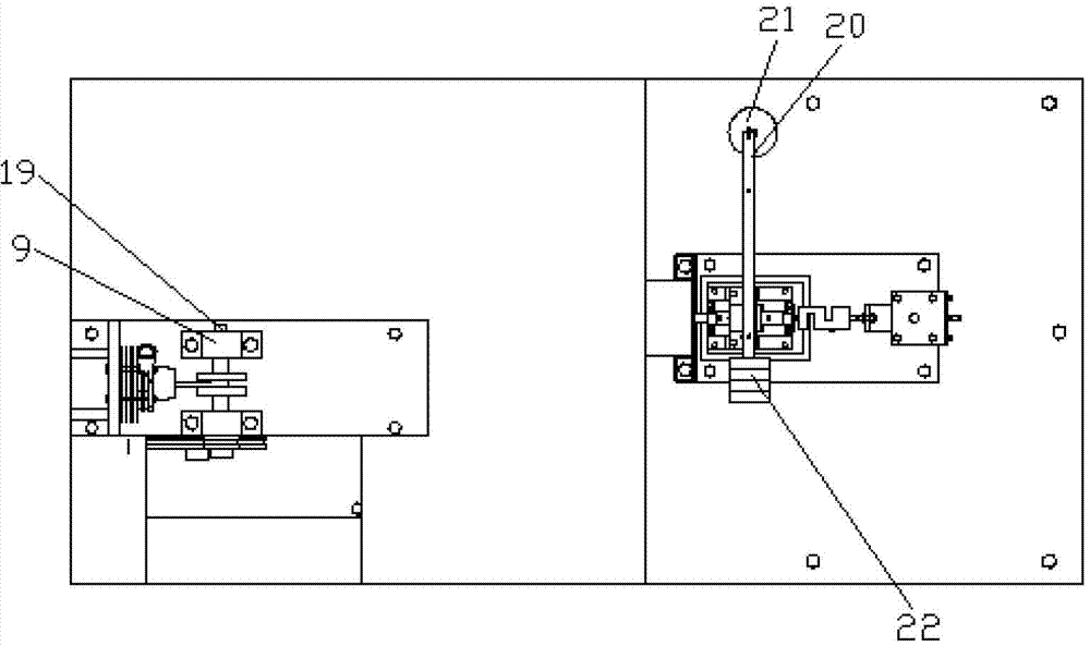
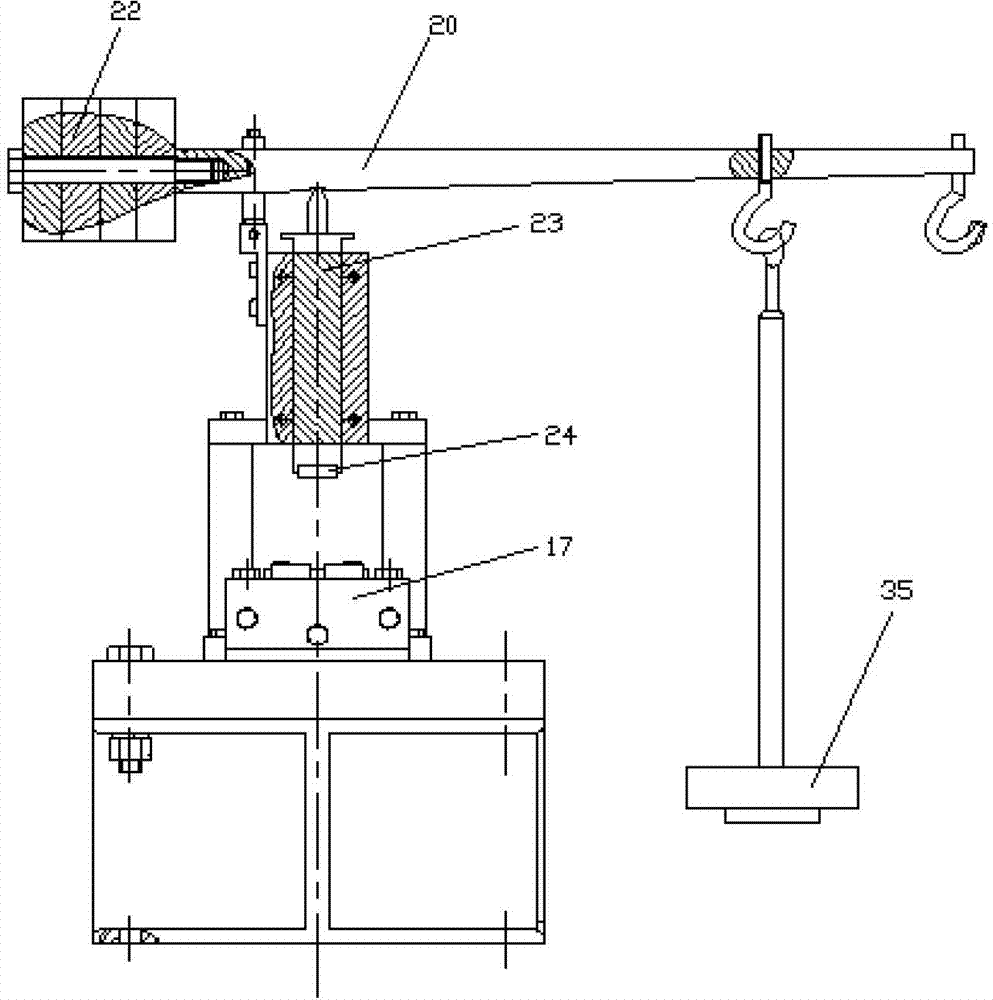
[0022] like figure 1 and figure 2 As shown, the friction and wear test bench is mainly composed of a power system, a transmission system, a loading system and a test system. The power is provided by the motor 2, and the motor 2 is fixed on the lower bracket 1; The second V-belt 11 is transmitted to the second small pulley 12, which drives the reformed diesel engine 13 to rotate. The diesel engine 13 changes the rotary motion into a linear motion, and connects the guide rod 30 to make the guide rod 30 do reciprocating motion. The guide rod 30 of the parts 31 and 29 reciprocates between the upper and lower cylinder liner test parts 24 and 25, and is manually loaded through the lever 20 and the weight plate 21; on the other hand, the power of the motor 2 is driven by the first The V belt 4 feeds the first small pulley 5, and the small pulley 5 drives the rotation of the crankshaft 19, and the crankshaft 19 drives the piston 33 to reciprocate in the piston cylinder 6 through the...


PUM


Abstract

The invention discloses a duplex piston ring-cylinder sleeve frictional wear test station. The duplex piston ring-cylinder sleeve frictional wear test station comprises an upper-layer support and a lower-layer support, wherein the lower-layer support is fixedly provided with an electromotor, a diesel engine and a base; a revolving shaft of the electromotor is fixedly provided with a large belt wheel, and the upper-layer support is provided with a supporting plate provided with bearing bases; the bearing bases are internally provided with bearings, the bearings are internally provided with a crankshaft, and the crankshaft is provided with a first small belt wheel connected with the large belt wheel through a first V belt; the supporting plate is fixedly provided with a transverse piston cylinder, a piston is matched to the inside of the piston cylinder, and a connecting rod is connected between the piston and the crankshaft; and an input shaft of the diesel engine is provided with a second small belt wheel connected with the large belt wheel through a second V belt, and the base is provided with a cylinder sleeve upper test specimen positioning clamping device, a cylinder sleeve lower test specimen positioning clamping device and a force transducer. The duplex piston ring-cylinder sleeve frictional wear test station provided by the invention utilizes a test station to carry out a lone frictional wear performance test on a cutting test specimen of a large-scale piston ring-cylinder sleeve or a small engine piston ring-cylinder sleeve, and the test specimens of the two piston ring-cylinder sleeve are simultaneously subjected to a frictional wear performance test.

Description

technical field [0001] The invention relates to a friction and wear test bench, in particular to a test bench for piston ring-cylinder liner friction and wear test. Background technique [0002] Piston ring-cylinder liner is one of the most important friction pairs of the engine, and its friction and wear performance directly affects the performance of the engine. At present, the main methods for evaluating the friction and wear performance of piston rings and cylinder liners are sample test method, bench test method and component simulation test method. Among them, the test parameters of the sample test method are easier to control, and the repeatability and stability are relatively good, but they are quite different from the actual situation of the piston ring-cylinder liner, and the simulation is poor; the bench test method uses a simulated load for the ignition test. The controllability of the conditions is good, and the simulation of the actual working conditions of th...

Claims


Application Information

Patent Timeline
Patent Type & Authority Applications(China)
IPC IPC(8): G01N3/56G01N3/02
Inventor 王伟刘勇刘小君刘焜王召唤
Owner HEFEI UNIV OF TECH
Why Eureka
Try Eureka