Multi-layer polyelectrolyte membranes
A polyelectrolyte, polymer technology, applied in solid electrolyte fuel cells, circuits, membrane technology, etc., can solve problems involving stability, strength and cost
- Summary
- Abstract
- Description
- Claims
- Application Information
AI Technical Summary
Problems solved by technology
Method used
Image

Examples
Embodiment 1
[0345] Example 1. PFCB and PFSA surface layer, 3 layers, coated together (AT)
[0346] Figure 5 is an optical image of a film with one PFCB-containing layer and two PFSA skin layers. refer to Figure 5 , were coated with 20 wt% DMAc solution from bottom to top, respectively (DE2020) (1.48-μm thick), perfluorocyclobutane (PFCB) (5.9-μm thick) coated with 11 wt% DMAc (N,N-dimethylacetamide) solution and coated with 20 wt% DMAc solution Covered (DE2020) (2.42 μm-thick). The total film thickness is about 10-12 μm thick. Coating details are as follows:
[0347] 1) The Ericsson coater was set at 40°C, with a clean glass plate or a piece of fluorinated ethylene-propylene (FEP)-coated polyimide backer film sheet as a vacuum platen ( The base on the vacuum platen);
[0348]2) Place a set of coating Bird applicators in the following order: one, 3 mil (10" coat width) applicator with masking tape shim, one, with Mylar (32mm- thick) 3 mil (9" coat width) applicator with spacer...
Embodiment 2
[0350] Example 2. PFCB and PFSA surface layer, 3 layers, layer by layer coating (LBL)
[0351] Figure 6 Optical images of films with one PFCB-containing layer and two PFSA skin layers are provided. refer to Figure 6 , were coated with 20 wt% DMAc solution from bottom to top, respectively (DE2020) (3.31-μm thick), perfluorocyclobutane (PFCB) (6.7-μm thick) coated with 11 wt% DMAc solution and (DE2020) (3.6-μm thick). The total film thickness is about 13-14-μm thick. Coating details are as follows:
[0352] 1) The coater was set at 40°C, with a clean glass plate or a piece of fluorinated ethylene-propylene (FEP)-coated polyimide base film sheet as the substrate on the vacuum platen. The coating speed was set at 12.5 mm / s and the coating direction was from left to right.
[0353] 2) The first floor (DE2020) Apply with a 1 mil Bird applicator (8" coat width) and dry at 40°C;
[0354] 3) The second PFCB ionomer layer was coated with a 3 mil Bird applicator (9" coating...
Embodiment 3
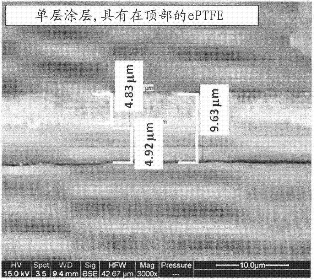
[0357] Example 3. PFCB and PFSA surface layer, layer by layer coating (LBL), ePTFE support in the middle
[0358] Figure 7 Optical images of membranes with one PFCB-containing layer and two PFSA skin layers and one ePTFE (expanded polytetrafluoroethylene) support layer are provided. The coated substrate used in this example was a 26-μm-thick polyimide film with a 2-μm-thick fluorinated ethylene-propylene (FEP) topcoat on both sides (total substrate film thickness is 30 μm). refer to Figure 7 , from bottom to top were coated with 10wt% isopropanol (IPA) solution (DE2020) (1.61-μm thick), perfluorocyclobutane (PFCB) (5.17-μm thick) coated with a 7 wt% DMAc solution, followed by ionomer-filled expanded polytetrafluoroethylene (ePTFE) Membranes of the support layer (3.84-μm thick) and coated with 5 wt% isopropanol solution (DE2020) (1.07-μm thick). The total film thickness is about 12-μm thick. Coating details are as follows:
[0359] 1) The coater was set at room temp...
PUM
 Abstract
Description
Claims
Application Information
 - R&D
- Intellectual Property
- Life Sciences
- Materials
- Tech Scout
- Unparalleled Data Quality
- Higher Quality Content
- 60% Fewer Hallucinations
Browse by: Latest US Patents, China's latest patents, Technical Efficacy Thesaurus, Application Domain, Technology Topic, Popular Technical Reports.
© 2025 PatSnap. All rights reserved.Legal|Privacy policy|Modern Slavery Act Transparency Statement|Sitemap|About US| Contact US: help@patsnap.com