Tooth-groove-type connection structure of upper-layer inner wallboard of assembly-type shear wall and lower-layer inner wallboard of assembly-type shear wall

A technology for connecting structures and inner wall panels, applied in the direction of walls, building components, building structures, etc., can solve the problems of difficult to guarantee welding quality, high construction accuracy requirements, and concentrated force at horizontal joints, and achieve accurate positioning and reliability. Simple, improved shear resistance, overall performance improvement effect

Active Publication Date: 2013-08-21
TIANJIN UNIV RES INST OF ARCHITECTRUAL DESIGN & URBAN PLANNING +1
View PDF4 Cites 31 Cited by
  • Summary
  • Abstract
  • Description
  • Claims
  • Application Information

AI Technical Summary

Problems solved by technology

Sleeve grouting connection has problems such as high cost of sleeve, high construction precision requirements, and unsuitability for steel bars with thinner cross-sections; steel bar welding connection has problems such as heavy on-site welding workload and difficult to guarantee welding quality; indirect lap joint grouting Anchor connections have problems such as difficult on-site construction and difficulty in guaranteeing the quality of reserved holes. Therefore, the prefabrication rate of interior walls in prefabricated structures is low, and after hoisting, cast-in-place structures n

Method used


Image

  • Tooth-groove-type connection structure of upper-layer inner wallboard of assembly-type shear wall and lower-layer inner wallboard of assembly-type shear wall
  • Tooth-groove-type connection structure of upper-layer inner wallboard of assembly-type shear wall and lower-layer inner wallboard of assembly-type shear wall
  • Tooth-groove-type connection structure of upper-layer inner wallboard of assembly-type shear wall and lower-layer inner wallboard of assembly-type shear wall

Examples


Embodiment Construction

[0023] In order to further understand the invention content, characteristics and effects of the present invention, the following examples are given, and detailed descriptions are as follows in conjunction with the accompanying drawings:

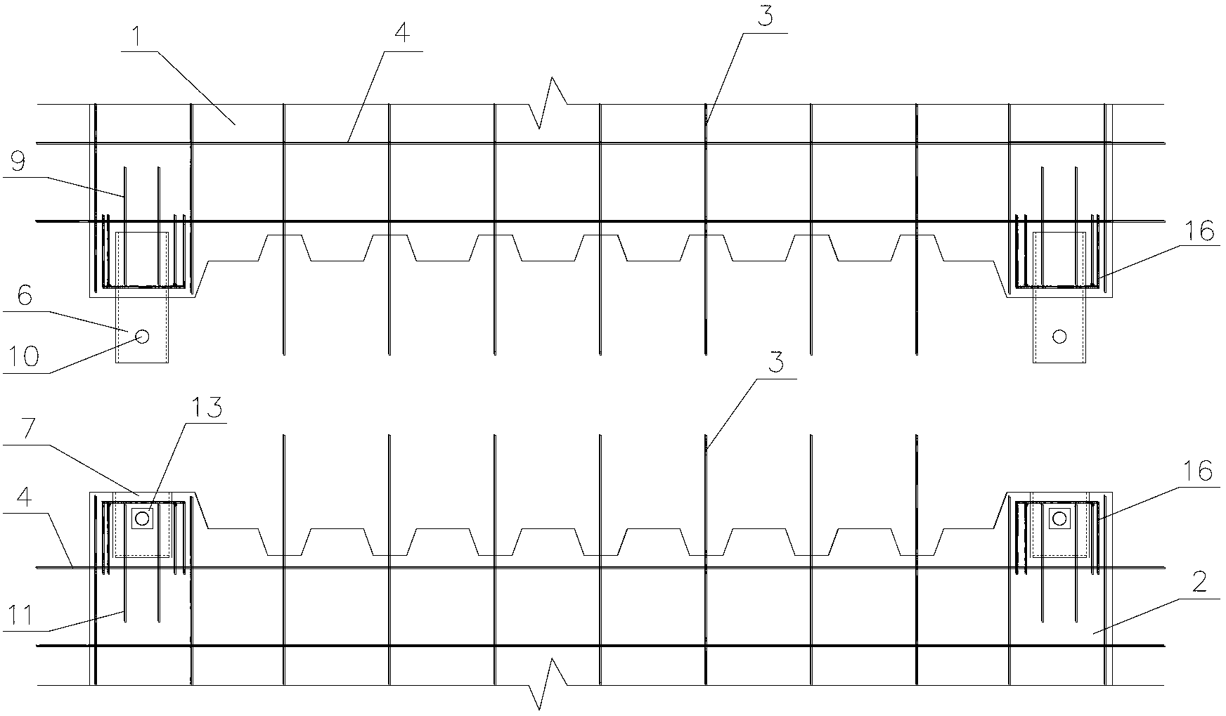
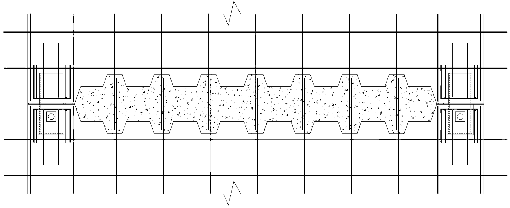
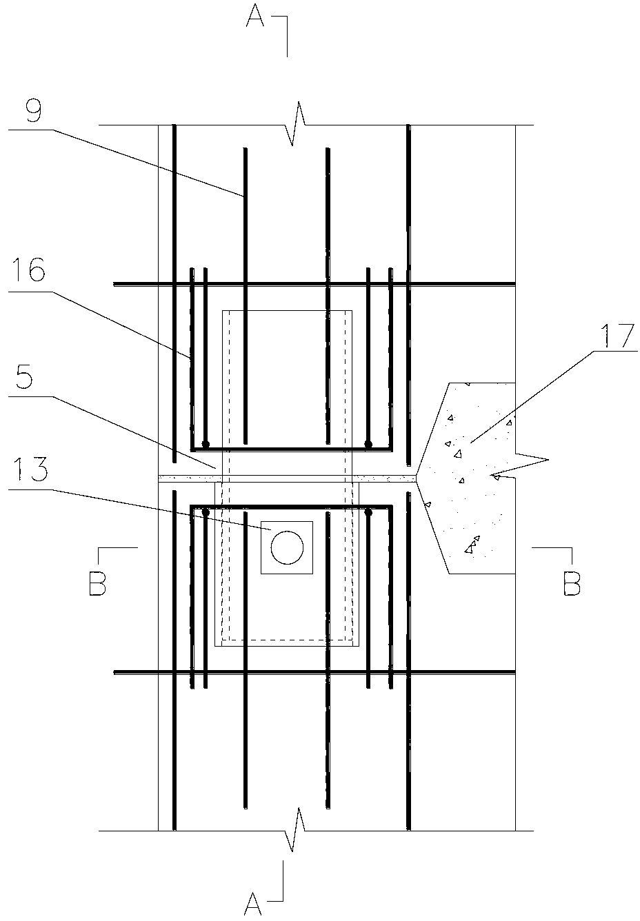
[0024] see Figure 1 to Figure 8 , a prefabricated shear wall interior wall panel upper and lower alveolar connection structure, each interior wall panel includes contact positioning structures 5 of two upper interior wall panels and a post-cast concrete structure 17 respectively arranged at its two ends, so that The post-cast concrete structure 17 is located between the two contact positioning structures 5; the upper inner wall panel 1 and the lower inner wall panel 2 are both prefabricated parts. An upper groove is formed on the bottom surface of the upper inner wall panel 1, and an upper toothed groove is formed at the bottom of the upper inner wall panel, and the vertically distributed steel bars 3 of the upper inner wall panel protrude f...


PUM


Abstract

The invention discloses a tooth-groove-type connection structure of an upper-layer inner wallboard of an assembly-type shear wall and a lower-layer inner wallboard of the assembly-type shear wall. Each inner wallboard comprises two contact locating structures of the upper-layer inner wallboard which are respectively arranged at two ends of each wallboard and a post-pouring concrete structure. The post-pouring concrete structure is located between the two contact locating structures. Upper grooves are formed in the bottom surface of the upper-layer inner wallboard, upper tooth-shaped grooves are formed in the bottoms of the upper grooves, and vertically-distributed rebars of the upper-layer inner wallboard stretch out from the upper grooves. Lower grooves are formed in the top surface of the lower-layer inner wallboard, lower tooth-shaped grooves are formed in the bottoms of the lower grooves, and vertically-distributed rebars of the lower-layer inner wallboard stretch out from the lower grooves. When the upper-layer inner wallboard is connected with the lower-layer inner wallboard, notches of the upper grooves are connected with notches of the lower grooves in a butt joint mode, forming grooves of the post-pouring concrete structure are formed, and the vertically-distributed rebars of the lower-layer inner wallboard and the vertically-distributed rebars of the upper-layer inner wallboard are correspondingly connected in a lap joint mode. The tooth-groove-type connection structure of the upper-layer inner wallboard of the assembly-type shear wall and the lower-layer inner wallboard of the assembly-type shear wall is easy and convenient to construct and reliable in structure.

Description

technical field [0001] The invention relates to the field of building structures, in particular to a tooth-groove connection structure of the lower and lower inner wall boards of an assembled shear wall. Background technique [0002] At present, the traditional cast-in-place shear wall structure has problems such as heavy on-site workload, waste of building materials, waste of building water, and serious environmental pollution. The vertical connection structure of the inner wall panels of the prefabricated shear wall structure mostly adopts sleeve grouting connection, steel bar welding connection and indirect lap joint grouting anchor connection. Sleeve grouting connection has problems such as high cost of sleeve, high construction precision requirements, and unsuitability for steel bars with thinner cross-sections; steel bar welding connection has problems such as heavy on-site welding workload and difficult to guarantee welding quality; indirect lap joint grouting Anchor...

Claims


Application Information

Patent Timeline
IPC IPC(8): E04B2/56
Inventor 张锡治安海玉凌光荣李义龙贾莉
Owner TIANJIN UNIV RES INST OF ARCHITECTRUAL DESIGN & URBAN PLANNING
Why Eureka
Try Eureka