
Coal-fired boiler shaft flue with sonic soot blowers

A technology for a sonic sootblower and a coal-fired boiler, which is applied in the field of coal-fired boilers, can solve the problems of large maintenance workload, large workload and cost, and will be stuck, and achieves low input efficiency and large maintenance workload. , the effect of improving safety

Inactive Publication Date: 2013-08-21
张晨
View PDF6 Cites 4 Cited by
  • Summary
  • Abstract
  • Description
  • Claims
  • Application Information

AI Technical Summary

Problems solved by technology

The heat exchangers are densely arranged in rows and groups in the flue. When the dust-carrying flue flows through these heat exchangers, a large amount of ash will be formed on them. The existence of a large amount of ash will reduce the exchange efficiency of the heat exchanger. Decrease, the heat in the flue gas will not be fully absorbed, which will directly lead to an increase in the exhaust gas temperature of the boiler, resulting in a decrease in boiler combustion efficiency and an increase in power generation costs. Therefore, soot blowing equipment must be installed on boilers in power plants
The traditional soot blowing equipment is long rod or short rod soot blower. This kind of equipment is mechanical steam soot blower. When blowing soot, the long rod or short rod soot blower is screwed into the boiler by mechanical transmission to spray a large amount of high pressure, High-temperature steam directly cleans the soot accumulated on the heat exchanger. This kind of soot blowing equipment has great disadvantages that cannot be overcome, and it has brought some economical and safety problems to the power plant.
The main disadvantages are as follows. One is that the heat exchanger will be stuck and leaked due to poor management.
Since the long-rod soot blower extends into the boiler in a cantilever shape, the rod deforms greatly during the soot blowing process. When the motor deforms too much, the long rod cannot be smoothly screwed in and out, and often gets stuck. Fault or thermal relay protection action, so that the soot blower motor stops working, sometimes the soot blower cannot be returned, and the soot blowing steam cannot be cut off in time, resulting in a furnace shutdown accident caused by blowing and leaking heat exchanger pipes
Second, the maintenance workload is large
Due to the high ambient temperature and a lot of dust on site, it is necessary to lubricate the refueling points of the soot blower in time, and this kind of work has to be checked repeatedly at intervals, and the maintenance workload is relatively heavy.
The third is blown heat exchanger
Generally, the pressure of long-stem steam sootblower is relatively high, and the steam flow rate is relatively large. After the anti-wear tile is blown, the heat exchanger will be directly blown. In particular, there are no anti-wear tiles on the sides of the heat exchangers that are deep up and down, and the pipes that have been blown and thinned must be cut and replaced, and the workload and cost are relatively large.
Fourth, soot blowing consumes a lot of steam and the operating cost is high
For a 1025t / h boiler and a 300MW boiler unit, soot blowing is performed twice a day, and the annual operating cost of all soot blowers is more than RMB 1.1 million. The operating cost of soot blowing air consumption is very high

Method used


Image

  • Coal-fired boiler shaft flue with sonic soot blowers
  • Coal-fired boiler shaft flue with sonic soot blowers
  • Coal-fired boiler shaft flue with sonic soot blowers

Examples


Embodiment Construction

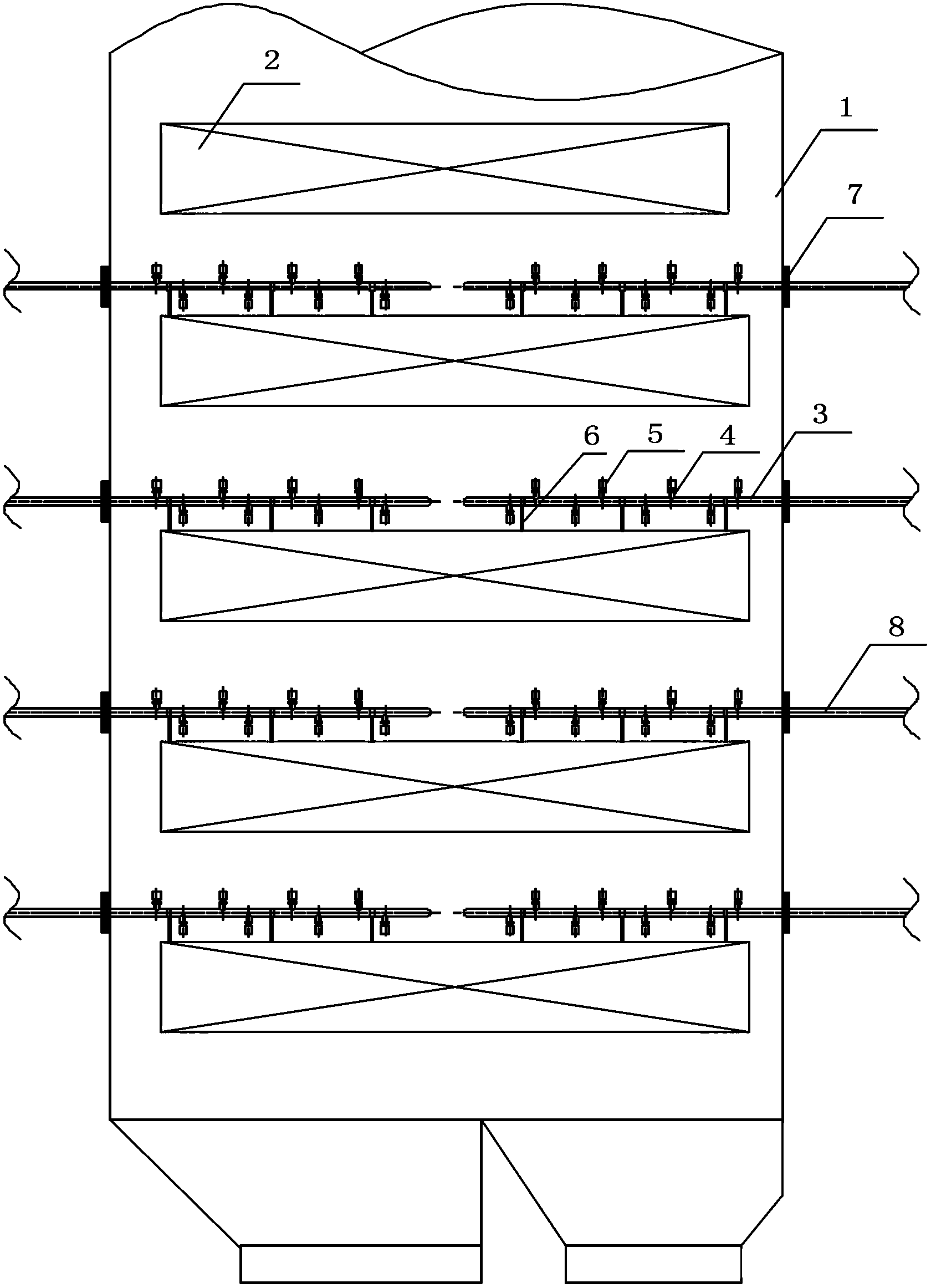
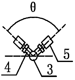
[0018] The shaft flue of the coal-fired boiler with the sonic soot blower proposed by the present invention has a structure such as figure 1 As shown, it includes a heat exchanger 2 , multiple pairs of main pipes 3 and multiple sonic soot blowers 5 . Multiple pairs of main tubes 3 are evenly distributed along the cross section of the boiler, one end of each pair of main tubes is opposite to each other and is in the center of the boiler, the other end of each pair of main tubes protrudes from the boiler wall, and the end of the main tube protrudes from the boiler wall The part is connected with the steam supply main pipe 8 outside the boiler by welding. The heat exchanger 2 and multiple pairs of main pipes 3 are installed in the shaft flue 1 at intervals, and the main pipes 3 are relatively fixed to the heat exchanger 2 through the main pipe support 6 . A plurality of sonic sootblowers 5 are installed on the main pipe 3 through the base pipe 4 .

[0019] The sonic soot blower...


PUM


Abstract

The invention relates to a coal-fired boiler shaft flue with sonic soot blowers and belongs to the technical field of coal-fired boilers. The coal-fired boiler shaft flue with the sonic soot blowers comprises heat exchangers, a plurality of pairs of primary pipes and the sonic soot blowers, wherein the pairs of primary pipes are evenly distributed along the cross section of a boiler, one end portions of each pair of primary pipes are opposite to each other and located in the center of the boiler, the other end portions of each pair of primary pipes extend out of the wall of the boiler respectively, and the end portions, extending out of the wall of the boiler, of the primary pipes are connected with steam supplying primary pipes outside the boiler in a welding mode. The heat exchangers and the pairs of primary pipes are installed in the shaft flue in a mutually spaced mode, and the primary pipes are fixed opposite to the heat exchangers through primary pipe supports. The sonic soot blowers are installed on the primary pipes through base pipes. The coal-fired boiler shaft flue has the advantages of being efficient, safe and energy-saving, promotes safety of the boiler, and can be free from daily tedious maintenance work. The sonic soot blowers are arranged in the boiler, and are free of rotating components and reliable in sealing.

Description

technical field [0001] The invention relates to a shaft flue of a coal-fired boiler with a sonic soot blower, belonging to the technical field of coal-fired boilers. Background technique [0002] The combustion of pulverized coal in coal-fired boilers in power plants produces a large amount of dust, which flows in the flue of the boiler with the flue gas. There are a large number of heat exchangers arranged in the flue of the boiler, and these heat exchangers absorb the heat in the flue gas to heat the Water or steam, air, etc. The heat exchangers are densely arranged in rows and groups in the flue. When the dust-carrying flue flows through these heat exchangers, a large amount of ash will be formed on them. The existence of a large amount of ash will reduce the exchange efficiency of the heat exchanger. Decrease, the heat in the flue gas will not be fully absorbed, which will directly lead to an increase in the exhaust gas temperature of the boiler, resulting in a decrease...

Claims


Application Information

Patent Timeline
IPC IPC(8): F23J3/02
Inventor 张晨韩淑华张举
Owner 张晨
Learn More