Visual navigation system of unmanned planes

A technology of navigation system and unmanned aerial vehicle, applied in navigation computing tools, motor vehicles, joint control, etc., can solve the problems of lack of geographic information flight environment, information lag, and high resource consumption, so as to improve information processing efficiency and improve communication. The effect of high performance and communication quality

Active Publication Date: 2013-08-21
TSINGHUA UNIV
View PDF3 Cites 37 Cited by
  • Summary
  • Abstract
  • Description
  • Claims
  • Application Information

AI Technical Summary

Problems solved by technology

The traditional UAV control method is to control the UAV through an external data communication link, and at the same time GPS (Global Positioning System, Global Satellite Positioning System) provides positioning information. The problem with this method is that, on the one hand, in Under conditions such as intentional interference, near the ground or in a canyon, covered by buildings, or even indoors (for micro drones), the communication link and GPS signal are easily blocked or lost, which will cause the drone to lose or temporarily lose Control, on the other hand, UAVs can only adapt to the requirements of a relatively structured task environment, and cannot solve autonomous control problems in dynamic, unorganized environments, such as sudden unexpected obstacles, flight environments lacking geographic information, etc.
However, there are also problems with this method. UAVs need to carry a lot of sensing equipment and process a large amount of data. At the same time, the data fusion processing has high real-time performance. UAVs have small payloads and limited resources and information processing capabilities
[0004] In view of the problems existing in a single UAV, multiple UAV clusters are use

Method used


Image

  • Visual navigation system of unmanned planes
  • Visual navigation system of unmanned planes
  • Visual navigation system of unmanned planes

Examples


Embodiment Construction

[0027] Embodiments of the present invention are described in detail below, examples of which are shown in the drawings, wherein the same or similar reference numerals designate the same or similar elements or elements having the same or similar functions throughout. The embodiments described below by referring to the figures are exemplary only for explaining the present invention and should not be construed as limiting the present invention.

[0028] Combine below Figure 1-Figure 6 The cooperative interaction method of the UAV cluster in the embodiment of the present invention is described in detail.

[0029] like figure 1 As shown, the cooperative interaction method of the UAV cluster according to the embodiment of the present invention includes the following steps:

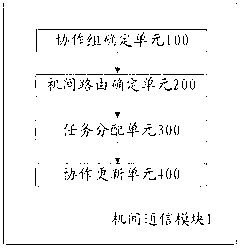
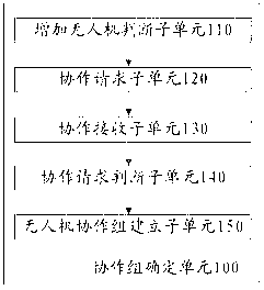
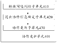
[0030] Step S101 , a certain UAV in the UAV cluster determines the UAVs within its communication coverage that meet the cooperation conditions, and establishes a UAV cooperation group based on the UAVs that m...


PUM


Abstract

The invention proposes a visual navigation system of unmanned planes, wherein a collaborative interaction method of an unmanned plane cluster comprises the following steps of: determining the unmanned plane of meeting the collaborative condition within the communication coverage by one unmanned plane in the unmanned plane cluster; building an unmanned plane collaboration group according to the unmanned plane meeting the collaborative condition; determining an interunit route among a plurality of unmanned planes in the unmanned plane collaboration group; distributing collaborative tasks to a plurality of unmanned planes in the unmanned plane collaboration group according to link state information of the interunit route; estimating the link state according to the movement states of the plurality of unmanned planes in the unmanned plane collaboration group; and updating the unmanned planes in the unmanned plane collaboration group and the collaborative task of each unmanned plane according to the assessment result. The visual navigation system of the unmanned planes has high reliability and high communication quality, and can well adapt to a communication environment of the unmanned plane cluster in visual navigation.

Description

technical field [0001] The invention relates to the technical field of unmanned aerial vehicles, in particular to a visual navigation system for unmanned aerial vehicles. Background technique [0002] UAVs are widely used in reconnaissance / surveillance, communication relay, electronic countermeasures, disaster prevention, emergency search and other application fields. The traditional UAV control method is to control the UAV through an external data communication link, and at the same time GPS (Global Positioning System, Global Satellite Positioning System) provides positioning information. The problem with this method is that, on the one hand, in Under conditions such as intentional interference, near the ground or in a canyon, covered by buildings, or even indoors (for micro drones), the communication link and GPS signal are easily blocked or lost, which will cause the drone to lose or temporarily lose Control, on the other hand, UAVs can only adapt to the requirements of ...

Claims


Application Information

Patent Timeline
IPC IPC(8): G01C21/20B64C19/02B64C39/00
Inventor 戴琼海刘慧
Owner TSINGHUA UNIV
Why Eureka
Try Eureka