Optical fiber with polarization function

An optical fiber and functional technology, applied in the laser field, can solve the problems of low production efficiency, high grinding accuracy and high coating requirements

Active Publication Date: 2013-08-21
XI'AN INST OF OPTICS & FINE MECHANICS - CHINESE ACAD OF SCI
View PDF1 Cites 4 Cited by
  • Summary
  • Abstract
  • Description
  • Claims
  • Application Information

AI Technical Summary

Problems solved by technology

[0004] D-type fiber polarizer is to finely grind the optical fiber into a D-shaped cross-section and then coat different metal films to produce polarization effects, but the requirements for grinding accuracy and coating are very high, and the production efficiency is low.

Method used


Image

  • Optical fiber with polarization function
  • Optical fiber with polarization function

Examples


Embodiment Construction

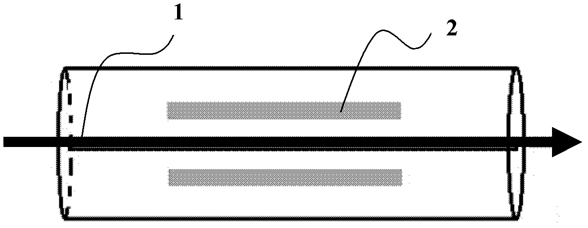
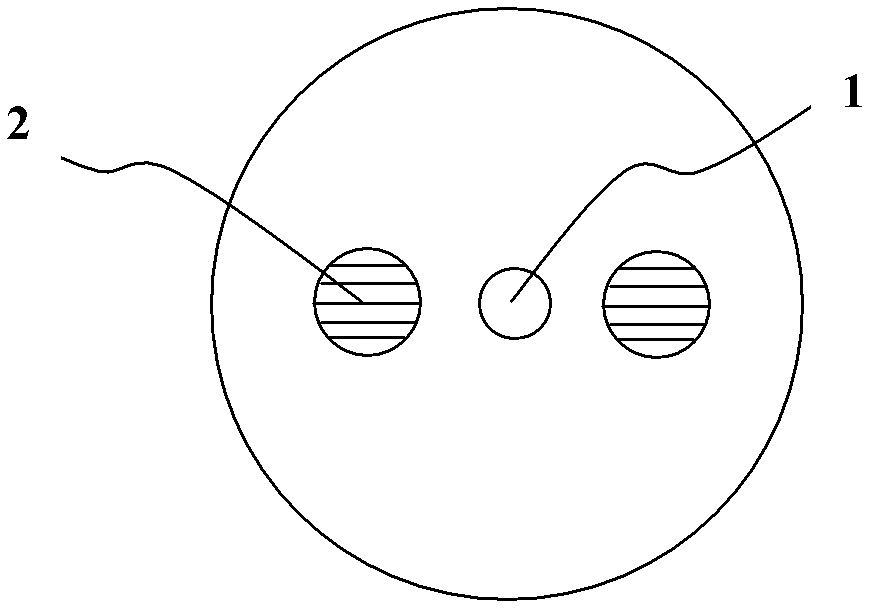
[0023] The working principle of the present invention is: under the action of the focused femtosecond pulsed laser, the quartz material will undergo multiphoton absorption at the laser focus and the action area of ​​the quartz material to generate plasma. When the plasma reaches a certain density, the material will be damaged, thereby changing The optical properties of quartz materials, and outside the laser focus, the laser intensity does not reach the multiphoton absorption threshold, and the material will not be damaged, so precise positioning processing can be realized within the material. Femtosecond pulse lithography with different parameters will produce two kinds of modification in quartz materials, that is, the change of refractive index or the induction of periodic nanostructures. The polarized light-guiding performance of the nano-grating produced by the parametric laser is also different. In the cladding near the core of the ordinary silica fiber, the nano-grating t...


PUM


Abstract

The invention relates to an optical fiber with a polarization function. The optical fiber comprises a nanometer grating arranged inside the optical fiber. The optical fiber with the polarization function is simple in optical structure, low in cost, large in band width range of working and high in extinction ratio.

Description

technical field [0001] The invention belongs to the field of laser technology, and relates to an optical fiber, in particular to an optical fiber with a polarization function. Background technique [0002] With the rapid development of today's optical fiber communication and optical fiber sensing technology, different types of optical fibers and active and passive optical fiber devices have become hot research topics. Among them, fiber optic polarizers have been widely used in fiber lasers, fiber optic sensing and measurement fields. Traditional fiber optic polarizers include the following types: polarizer-type fiber polarizers, D-type fiber polarizers, fused-taper fiber polarizers, etc. . [0003] The polarizer-type fiber polarizer is mainly composed of a pigtail, a polarizer, and a fiber collimator. The light in the fiber enters the fiber collimator, transforms into a parallel beam, and is perpendicular to the surface of the polarizer, resulting in linear polarization in ...

Claims


Application Information

Patent Timeline
IPC IPC(8): G02B6/024G02B6/02
Inventor 程光华赵卫白晶
Owner XI'AN INST OF OPTICS & FINE MECHANICS - CHINESE ACAD OF SCI
Why Eureka
Try Eureka