Fin type field effect transistor and preparation method thereof

The technology of field effect transistor and fin body is applied in the field of fin field effect transistor and its preparation, which can solve the problem of high sub-threshold slope and achieve the effects of improving gate control capability, low power consumption and fast switching speed

Inactive Publication Date: 2018-07-17
INST OF MICROELECTRONICS CHINESE ACAD OF SCI +1
View PDF5 Cites 0 Cited by
  • Summary
  • Abstract
  • Description
  • Claims
  • Application Information

AI Technical Summary

Problems solved by technology

[0004] The main purpose of the present invention is to provide a fin field effect transistor and its preparation method to solve the problem of high subthreshold slope of the fin field effect transistor in the prior art

Method used


Image

  • Fin type field effect transistor and preparation method thereof
  • Fin type field effect transistor and preparation method thereof
  • Fin type field effect transistor and preparation method thereof

Examples


Embodiment Construction

[0039] It should be noted that, in the case of no conflict, the embodiments of the present invention and the features in the embodiments can be combined with each other. The present invention will be described in detail below with reference to the accompanying drawings and examples.

[0040]In order to enable those skilled in the art to better understand the solutions of the present invention, the following will clearly and completely describe the technical solutions in the embodiments of the present invention in conjunction with the drawings in the embodiments of the present invention. Obviously, the described embodiments are only It is an embodiment of a part of the present invention, but not all embodiments. Based on the embodiments of the present invention, all other embodiments obtained by persons of ordinary skill in the art without making creative efforts shall fall within the protection scope of the present invention.

[0041] It should be noted that the terms "first"...


PUM


Abstract

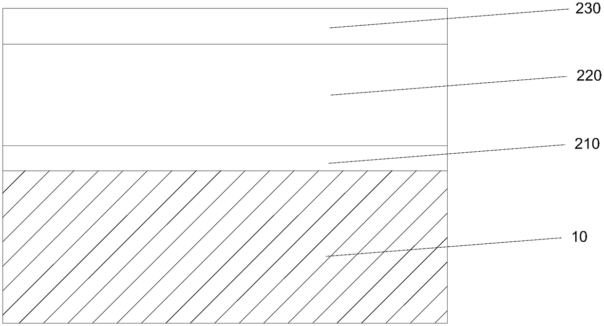
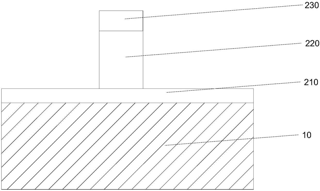
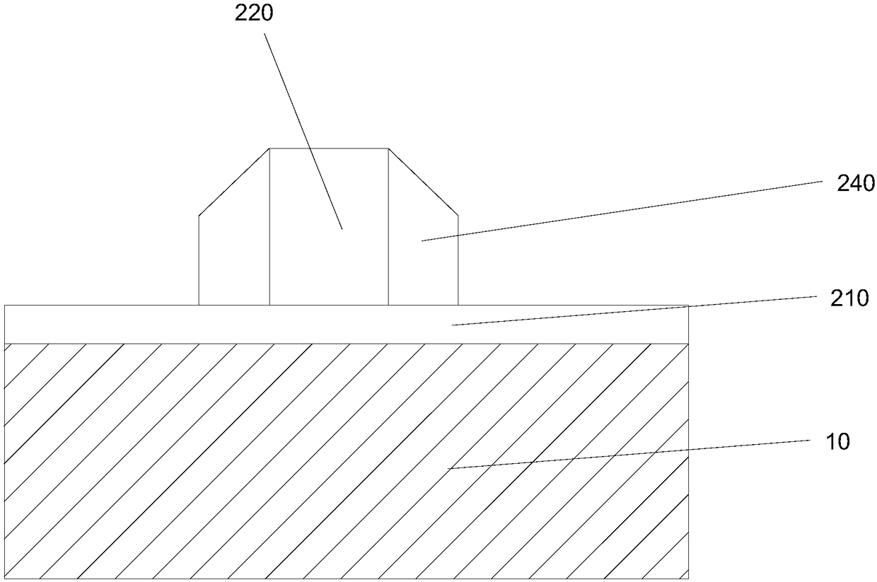
The invention provides a fin type field effect transistor and a preparation method thereof. The preparation method comprises the following steps of S1, forming a first fin body isolated from a substrate on the substrate, wherein the first fin body consists of a first region, a second region and a third region which are connected in sequence in the length direction; and S2, forming an interface oxide layer, a ferroelectric layer and a gate which are laminated around the exposed surface of the second region in sequence, wherein the preparation method also comprises the following steps of forminga source/drain in the first region and the third region, wherein the source/drain is connected with the two ends of the second region. By virtue of the preparation method, the gate control capabilityof the device is improved, electric leakage of the device is lowered, and the sub threshold value slope of the device can be greatly lower than 60mV/dec.

Description

technical field [0001] The invention relates to the technical field of semiconductors, in particular to a fin field effect transistor and a preparation method thereof. Background technique [0002] As devices continue to shrink, traditional Fin Field Effect Transistors (FinFETs) face severely degraded sub-threshold characteristics, sharply increased source-drain punch-through leakage currents, and gate-dielectric tunneling leakage currents, improving drive performance and reducing system power consumption. There are many serious challenges such as the contradictory requirements of voltage and statistical fluctuations of electrical parameters caused by process variation. Therefore, a steeper sub-threshold slope means that a lower threshold voltage and lower power consumption can be obtained. However, due to the limitation of its physical characteristics, the sub-threshold slope of traditional MOSFETs cannot be lower than 60mV / dec. [0003] How to provide a lower subthreshold...

Claims


Application Information

Patent Timeline
Patent Type & Authority Applications(China)
IPC IPC(8): H01L29/78H01L21/336H01L29/423
CPCH01L29/42356H01L29/66795H01L29/7855
Inventor 张青竹张兆浩殷华湘徐忍忍
Owner INST OF MICROELECTRONICS CHINESE ACAD OF SCI
Why Eureka
Try Eureka