Monitoring device of optical cable distribution boxes and monitoring system of optical cable distribution boxes
A technology of optical cable transfer box and monitoring device, which is applied in the direction of transmission system, electromagnetic wave transmission system, fiber mechanical structure, etc., to achieve the effect of low equipment cost, reduced unit cost, and simple device combination
- Summary
- Abstract
- Description
- Claims
- Application Information
AI Technical Summary
Problems solved by technology
Method used
Image

Examples
Embodiment 1
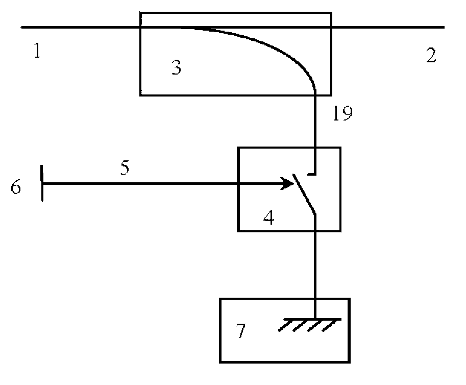
[0044] See figure 1 , Shown is an optical cable transfer box door opening monitoring device. The monitoring device is mainly composed of an optical fiber splitter 3, an optical switch 4 and an optical reflector 7. The optical fiber splitter 3 is arranged between the optical fiber monitoring input end 1 and the optical fiber monitoring output end 2 in the optical cable junction box to be monitored, and is used to separate an optical monitoring branch 19.
[0045] In order to separate the optical monitoring branch 19, the optical fiber splitter 3 may specifically adopt a fiber coupler or a planar waveguide optical splitter.
[0046] The optical splitting ratio between the optical monitoring branch end and the optical monitoring output end of the optical fiber splitter is between 0.1:99.9 and 5:95.
[0047] The optical switch 4 and the optical reflector 7 are sequentially connected in series on the optical monitoring branch 19, and the output end of the optical switch 4 cooperates with...
Embodiment 2
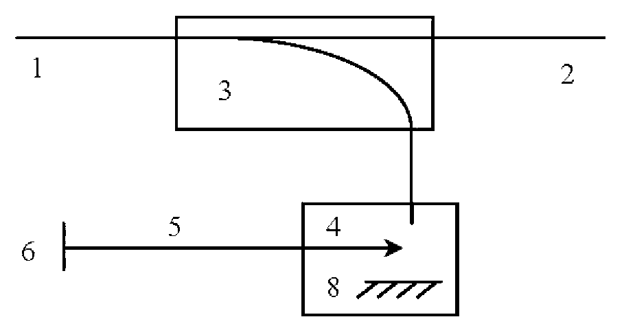
[0050] See figure 2 , Which shows the reflective switch type optical cable transfer box door open monitoring device provided by this example. The monitoring device in this example directly combines the fiber reflector and the optical switch. The optical switch 4 no longer has an output end, but an optical reflector 8 is installed in it, thereby forming a corresponding monitoring and control fiber reflector.
[0051] At the same time, the switch link 5 is linked by the door opening contact 6 to shading control the input light irradiated on the light reflector 8. The other structure is the same as the monitoring device in Example 1.
[0052] The monitoring device in this example uses the linkage of the door opening contact 6 and the switch link 5 to shading control the input light irradiated on the light reflector 8, thereby changing the intensity of the reflected light on the optical monitoring branch of the optical cable junction box. In this way, the strength and weakness of the ...
Embodiment 3
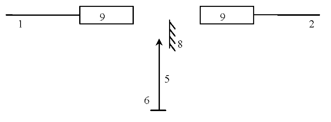
[0055] See image 3 , Which shows the transmission shielding type optical cable transfer box door opening monitoring device provided by this example. The device specifically includes two fiber collimating lenses 9 and a light reflecting mirror 8.
[0056] Two of the fiber collimating lenses 9 are respectively disposed at the fiber monitoring input end and the fiber monitoring output end of the fiber optic cable junction box, respectively, and the fiber collimating lens 9 can be a self-focusing lens or a collimating convex lens. The transmitted light is directly transmitted from the optical fiber monitoring input end 1 through the two optical fiber collimating lenses 9 and the free space between them to the optical fiber monitoring output end 2.
[0057] The light reflector 8 and the two optical fiber collimator lenses 9 are arranged in cooperation to reflect only part of the light beams collimated and expanded between the two optical fiber collimator lenses. At the same time, the d...
PUM
 Abstract
Description
Claims
Application Information
 - R&D
- Intellectual Property
- Life Sciences
- Materials
- Tech Scout
- Unparalleled Data Quality
- Higher Quality Content
- 60% Fewer Hallucinations
Browse by: Latest US Patents, China's latest patents, Technical Efficacy Thesaurus, Application Domain, Technology Topic, Popular Technical Reports.
© 2025 PatSnap. All rights reserved.Legal|Privacy policy|Modern Slavery Act Transparency Statement|Sitemap|About US| Contact US: help@patsnap.com