Dynamic tunable filter based on polarization controller and waveguide grating and tuning method
A polarization controller and tuning filter technology, which is applied to optical waveguides, optics, instruments, etc., can solve the problems of high insertion loss, poor stability of electro-optic polymer waveguide grating devices, and slow tuning speed, and achieves low insertion loss, Excellent tunable performance and good stability
- Summary
- Abstract
- Description
- Claims
- Application Information
AI Technical Summary
Problems solved by technology
Method used
Image
Examples
Embodiment 1
[0035] 1. Dynamically tunable filter
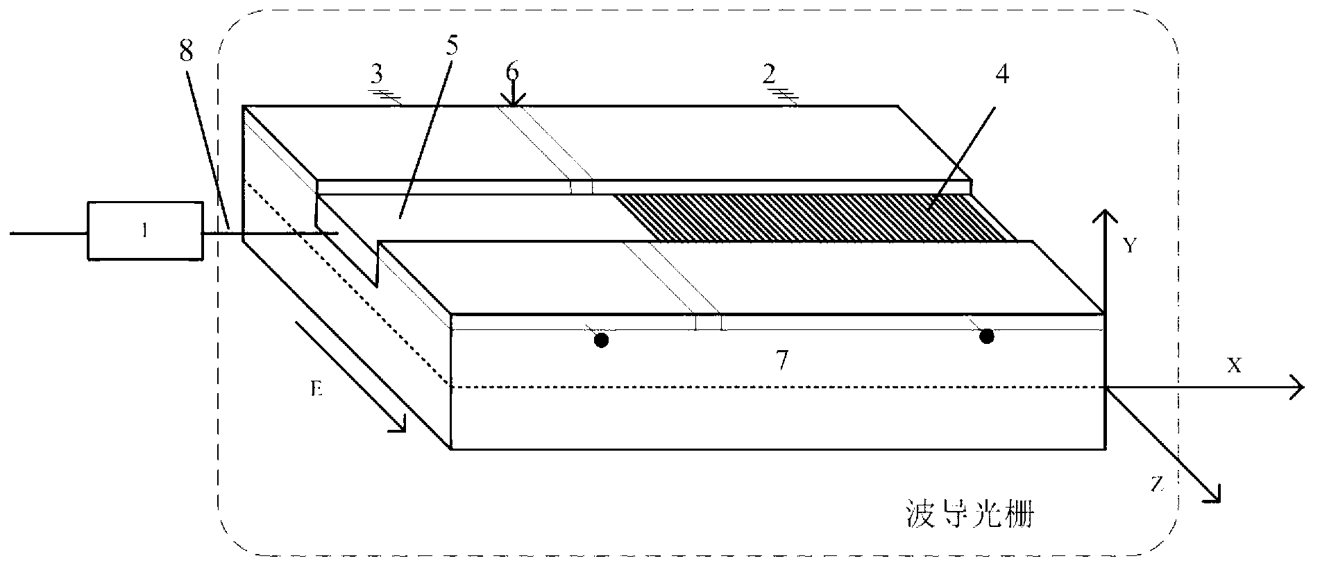
[0036] Such as figure 1 As shown, it is a dynamically tunable filter based on a polarization controller and a waveguide grating. Its structure includes two parts: a polarization controller and a waveguide grating. The light intensity of the reflected wave is controlled, and the resonant wavelength and the phase of the reflected wave are controlled by the waveguide grating part.
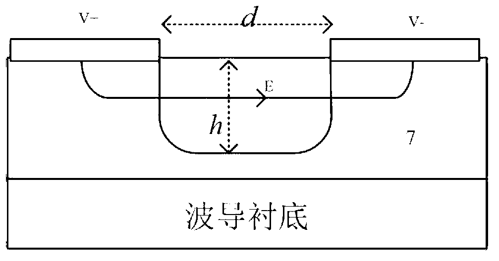
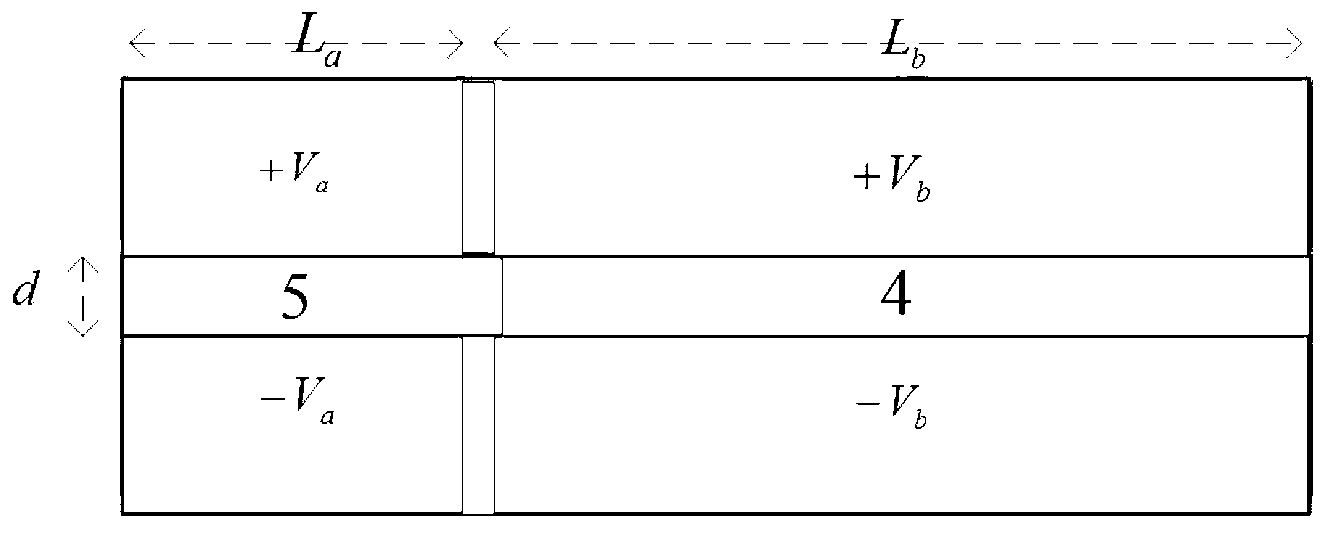
[0037] The waveguide grating includes a base 7 of the waveguide grating, a grooved waveguide 5 and a wrinkled-order Bragg grating 4 are respectively arranged on the middle upper part of the substrate, and phase adjustment electrodes 3 (V a ), wavelength tuning electrodes 2 (V b ), the phase adjustment electrode (V a ) and the wavelength tuning electrode (V b ) is provided with an insulating (isolating) strip 6 between them.
[0038] The waveguide grating uses X-cut lithium niobate crystal as the substrate, and the substrate is placed in octadecanoic acid (CH...
Embodiment 2
[0052] In this embodiment, the grooved waveguide width d=7μm in the present invention, the wrinkled order Bragg grating length L b =10.36mm, the grating period Λ=362.3nm, the etching depth w=50nm, the etching duty ratio is 1 / 2, and the voltage on both sides is v b . The length of the grooved waveguide without grating written is L a =3.45mm, the voltage on both sides is v a . The spacing between the electrodes is equal to the width of the waveguide.
[0053] Figure 7 It reflects the tuning relationship between the filter reflection spectrum and the applied voltage under the parameter settings in Example 2. It can be seen from the figure that when the applied voltage changes from -100v to +100v, the resonance wavelength tuning range is 3nm, and the tuning sensitivity is 15pm / v. Reducing the etch depth greatly degrades the filtering performance, and reducing the waveguide width (electrode spacing) increases the tuning sensitivity for reflected wavelengths.
[0054] Figur...
PUM
 Abstract
Description
Claims
Application Information
 - R&D
- Intellectual Property
- Life Sciences
- Materials
- Tech Scout
- Unparalleled Data Quality
- Higher Quality Content
- 60% Fewer Hallucinations
Browse by: Latest US Patents, China's latest patents, Technical Efficacy Thesaurus, Application Domain, Technology Topic, Popular Technical Reports.
© 2025 PatSnap. All rights reserved.Legal|Privacy policy|Modern Slavery Act Transparency Statement|Sitemap|About US| Contact US: help@patsnap.com


