Adjustable program automatically controlled displayer
A programmable controller and adjustable technology, applied in the direction of instruments, electrical digital data processing, digital data processing parts, etc., can solve the problems of cervical spine strain, achieve the effect of promoting health, simple structure, and convenient use
- Summary
- Abstract
- Description
- Claims
- Application Information
AI Technical Summary
Problems solved by technology
Method used
Image
Examples
Embodiment 1
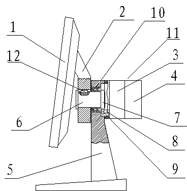
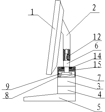
[0021] Such as figure 1 and figure 2 As shown, an adjustable program automatic control display includes a display screen 1 and a support, and also includes a programmable logic controller (PLC) and a signal collector. The support is composed of an upper support 2 and a lower support 5. The lower support The upper part of the seat 5 is provided with a casing 11, and the casing 11 is provided with a stepping motor 4 and a reducer 3 connected with the stepping motor 4 (the transmission ratio of the reducer is 1-100), and the shaft hole of the lower support 5 is installed Radial bearing 10 is arranged, and rotating shaft 6 is installed in radial bearing 10 . The display screen 1 is connected with the upper support 2, and the upper support 2 is installed on the rotating shaft 6 and connected with the rotating shaft 6 through the key 12; the end of the rotating shaft 6 is equipped with a large gear 7, and the output shaft 8 of the reducer 3 is equipped with a small Gear 9, pinion...
Embodiment 2
[0027] Such as figure 2 and image 3 As shown, an adjustable program automatic control display includes a display screen 1 and a support, and also includes a programmable logic controller (PLC) and a signal collector. The support is composed of an upper support 2 and a lower support 5. The lower support The upper part of the seat 5 is provided with a box body 15, and the box body 15 is provided with a stepping motor 4 and a reducer 3 connected with the stepping motor 4 (the transmission ratio of the reducer is 1-100), the reducer 3 has an output shaft 8, and the output The pinion 9 is installed on the shaft 8; the upper end of the box body 15 has a bearing hole, and a thrust bearing 14 is installed in the bearing hole, and a rotating shaft 6 is installed in the thrust bearing 14, and a large gear 7 is installed on the lower end of the rotating shaft 6, and the large gear 7 is meshed with pinion 9 transmission. The upper end of rotating shaft 6 is inserted in the shaft hole ...
Embodiment 3
[0033]On the basis of Embodiment 1, the lower end of the lower support 5 has an elbow, a bracket is installed on the bottom plate, and a rotating shaft 6 is installed on the bracket. The left end of the rotating shaft 6 squeezes into the hole of the elbow and is connected with the elbow through a key 12. , the right end of the rotating shaft 6 is equipped with a large gear 7, and the output shaft 8 of the reducer 3 connected with the stepping motor 4 is equipped with a small gear 9, and the small gear 9 and the large gear 7 are meshed for transmission, and the control display is flipped forward and backward at a certain angle. With embodiment 1.
PUM
 Abstract
Description
Claims
Application Information
 - R&D
- Intellectual Property
- Life Sciences
- Materials
- Tech Scout
- Unparalleled Data Quality
- Higher Quality Content
- 60% Fewer Hallucinations
Browse by: Latest US Patents, China's latest patents, Technical Efficacy Thesaurus, Application Domain, Technology Topic, Popular Technical Reports.
© 2025 PatSnap. All rights reserved.Legal|Privacy policy|Modern Slavery Act Transparency Statement|Sitemap|About US| Contact US: help@patsnap.com


