A Lorentz force demonstrator

A demonstrator and container technology, which is applied in the field of Lorentz force demonstrators, can solve the problems of demonstrating Lorentz force, etc., and achieve the effects of easy operation, obvious effect, and low production cost

Inactive Publication Date: 2015-09-16
HUZHOU TEACHERS COLLEGE
View PDF5 Cites 0 Cited by
  • Summary
  • Abstract
  • Description
  • Claims
  • Application Information

AI Technical Summary

Problems solved by technology

In actual physics teaching, there is no special instrument to demonstrate the Lorentz force, teachers can only use animation to illustrate

Method used


Image

  • A Lorentz force demonstrator

Examples


Embodiment 1

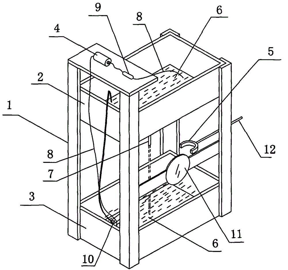
[0018] Such as figure 1 As shown, a Lorentz force demonstrator includes a bracket 1 and an upper container 2 , a lower container 3 , a power supply 4 , and a ferromagnet 5 arranged on the bracket 1 . There is a water pump 10 in the lower container 3 , and the water outlet of the water pump 10 is located in the upper container 2 . The upper container 2 and the lower container 3 are equipped with a conductive liquid 6, which can be a strong electrolyte solution such as sodium chloride solution. After sodium chloride is dissolved in water, free-moving sodium ions and chloride ions are produced. After electrification, the sodium ions and chlorine All ions move in a directional motion. The upper container 2 communicates with a vertically arranged conduit 7, the conductive liquid 6 in the upper container 2 flows out from the conduit 7 to form a water column and falls to the lower container 3, a wire 8 is connected to each end of the power supply 4, and one end of the power supply 4...


PUM


Abstract

The invention belongs to teaching instruments and particularly relates to a Lorentz force demonstrating instrument. The Lorentz force demonstrating instrument comprises a support (1), an upper container (2), a lower container (3), a power source (4) and a ferromagnet (5), wherein the upper container (2), the lower container (3), the power source (4) and the ferromagnet (5) are arranged on the support (1), electric conducting liquid (6) is filled in the upper container (2) and the lower container (3), the upper container (2) is communicated with a guide pipe (7) arranged vertically, the electric conducting liquid (6) of the upper container flows out of the guide pipe (7), forms a water column and falls into the lower container (3), two ends of the power source (4) are respectively connected with a lead wire (8), the lead wire (8) at one end of the power source (4) is steeped into the electric conducting liquid (6) of the upper container (2), the lead wire (8) at the other end of the power source (4) is steeped into the electric conducting liquid (6) of the lower container (3), and the ferromagnet (5) is located between the upper container (2) and the lower container (3). The Lorentz force demonstrating instrument enables students to visually watch Lorentz force born by charged particles, and is helpful in knowledge grasp.

Description

technical field [0001] The invention belongs to teaching instruments, in particular to a Lorentz force demonstration instrument. Background technique [0002] Charged particles experience the Lorentz force in a magnetic field. The formula of Lorentz force is F=qvB, where q and v are the electric quantity and velocity of the point charge respectively, and B is the magnetic induction intensity where the point charge is located. The electron beam emitted from the cathode, under the action of high voltage between the cathode and the anode, bombards the strip-shaped fluorescent screen to excite fluorescence, and the trajectory of the electron beam movement can be displayed on the oscilloscope. When there is no external magnetic field, the electron beam advances in a straight line. If the ray tube is placed between the two poles of the hoof magnet, the trajectory of the electron beam movement displayed on the fluorescent screen will be bent. In actual physics teaching, there is ...

Claims


Application Information

Patent Timeline
Patent Type & Authority Patents(China)
IPC IPC(8): G09B23/18
Inventor 呼格吉乐韩秋红张天声陈劲光
Owner HUZHOU TEACHERS COLLEGE
Why Eureka
Try Eureka