
Field emission apparatus and hand-held nondestructive inspection apparatus

A field emission and electron emission technology, which is applied in irradiation devices, X-ray tubes, X-ray equipment, etc., can solve problems such as difficult cooling, easy damage, and time-consuming production, and achieve the effect of improving heat dissipation

Inactive Publication Date: 2013-08-21
MICRO X JAPAN
View PDF14 Cites 3 Cited by
  • Summary
  • Abstract
  • Description
  • Claims
  • Application Information

AI Technical Summary

Problems solved by technology

[0044] In addition, in the X-ray generator as one of the field emission devices, the emitter, the counter cathode, and the focusing electrode have been arranged in a glass container, which has problems such as easy damage, time-consuming manufacturing, and difficulty in cooling.

Method used


Image

  • Field emission apparatus and hand-held nondestructive inspection apparatus
  • Field emission apparatus and hand-held nondestructive inspection apparatus
  • Field emission apparatus and hand-held nondestructive inspection apparatus

Examples


Embodiment Construction

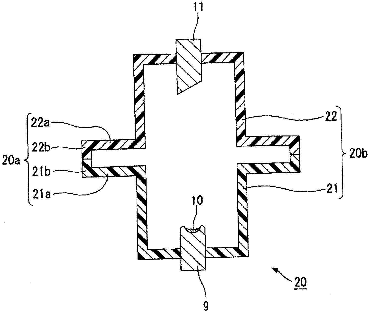
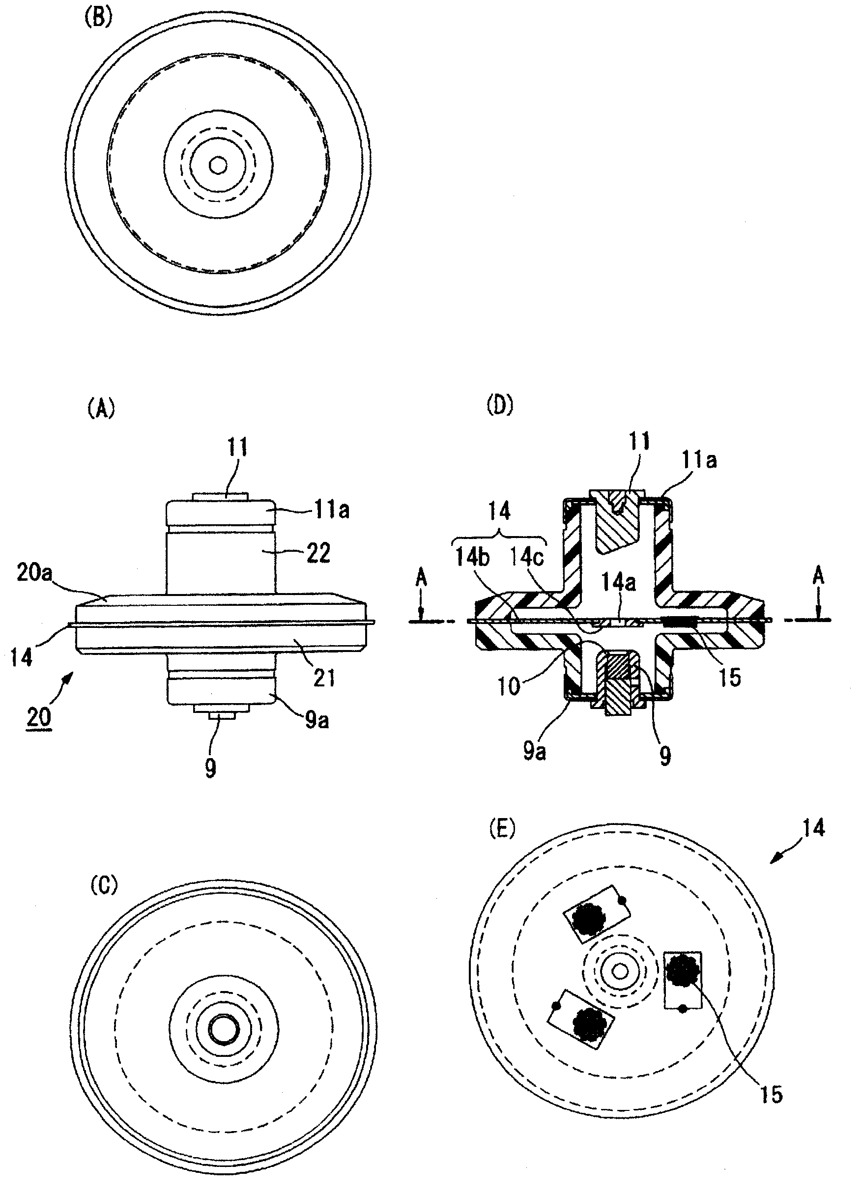
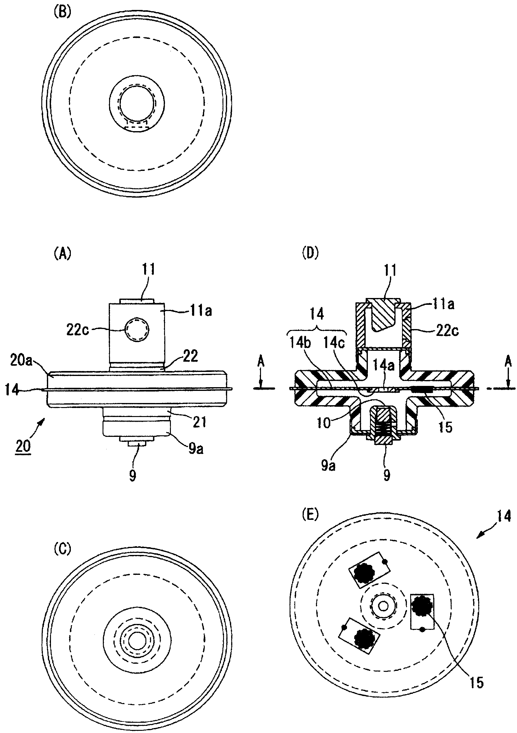
[0086] Hereinafter, embodiments of the field emission device in the present invention will be described in detail with reference to the drawings and the like. It should be noted that, with regard to Figure 20 ~ Figure 22 For the same structures, for example, the same symbols are used, and detailed descriptions are appropriately omitted.

[0087] The first invention is made by discovering that the basis does not merely take for example Figure 21 As shown, the side wall of the cylindrical container is elongated along the electron beam radiation direction, but a part between the cold cathode and the anode in the cylindrical container (for example, where the focusing electrodes such as electron lenses are located) The side wall of the portion) is enlarged in diameter along a direction perpendicular to the electron beam radiation direction, and has a flange portion in which a hollow portion is formed by the enlarged side wall (the hollow portion and the inside of the vacuum cont...


PUM


Abstract

In the present invention, heat dissipation is improved by extending the creeping distance in a vacuum vessel according to the size of a flange part, without lengthening the vacuum vessel in the direction in which an electron beam is emitted. A vacuum vessel (20) in which a flange portion (20a) having a hollow portion between a cold cathode (9) and an anode (11) is formed is used. One example is a vacuum vessel (20) in which a cold cathode vessel (21) and an anode vessel (22), both cylindrically shaped, are communicated with each other and a hollow flange portion (20a) is formed between the vessels (21, 22). A focusing electrode (14) and a getter material (15), for example, are disposed in the hollow portion of the flange portion (20a). A cold cathode (9) which has a guard electrode on the outer side of the periphery of a carbon film structure (10) formed on a substrate (7) may be used. The carbon film structure (10) may be formed in the middle of an electrode surface of the substrate (7).

Description

technical field [0001] The present invention relates to a field emission device and a portable non-destructive inspection device equipped with electron emitters applicable to various devices such as electron tubes, lighting devices, and X-ray devices. Background technique [0002] Field emission is a phenomenon in which electrons are emitted into a vacuum by concentration of an electric field, and attention has been drawn to electron emitters for this field emission, for example, carbon nanotubes. The carbon nanotubes are extremely slender and have excellent field emission characteristics due to their high aspect ratios, so field electron emission devices can be obtained, and they are studied and applied to various field emission devices such as electron tubes and lighting devices. [0003] Field emission characteristics (IV characteristics) refer to the indicated voltage V and field emission current (emitter current) I when a voltage V is applied between the counter anode (...

Claims


Application Information

Patent Timeline
Patent Type & Authority Applications(China)
IPC IPC(8): H01J5/02G21K5/00G21K5/02H01J1/46H01J7/24H01J35/16H05G1/04
CPCH01J35/065H01J2201/30469H01J2235/062H01J2237/16H01J19/54H01J19/42
Inventor 石黑义久羽场方芳
Owner MICRO X JAPAN
Learn More