
Ignition coil having coupling device

A technology of ignition coil and connecting device, applied in the direction of engine ignition, spark ignition controller, spark plug, etc., can solve the problems of limited selection, inability to ensure ignition coil, etc., to ensure prestress, cost economy, continuous and reliable, and prevent surrounding media. and environmental impact

Inactive Publication Date: 2013-08-21
ROBERT BOSCH GMBH
View PDF3 Cites 1 Cited by
  • Summary
  • Abstract
  • Description
  • Claims
  • Application Information

AI Technical Summary

Problems solved by technology

In addition, however, a certain degree of elasticity is also required within the connection, since due to external temperature changes and expansion due to heat, a permanently fixed position of the ignition coil in the engine block cannot be ensured
Furthermore, the chemical loading of lubricants and combustion gases, as well as external influences and cleaning agents, limits the selection of suitable materials for the manufacture of ignition coils, especially their housings

Method used


Image

  • Ignition coil having coupling device
  • Ignition coil having coupling device
  • Ignition coil having coupling device

Examples


Embodiment Construction

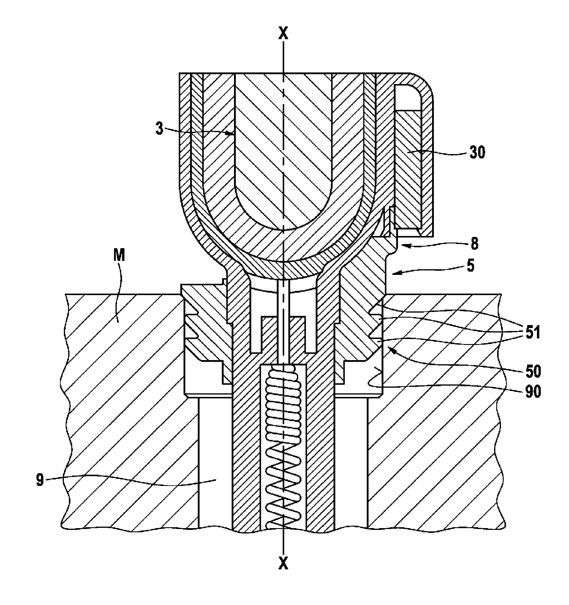
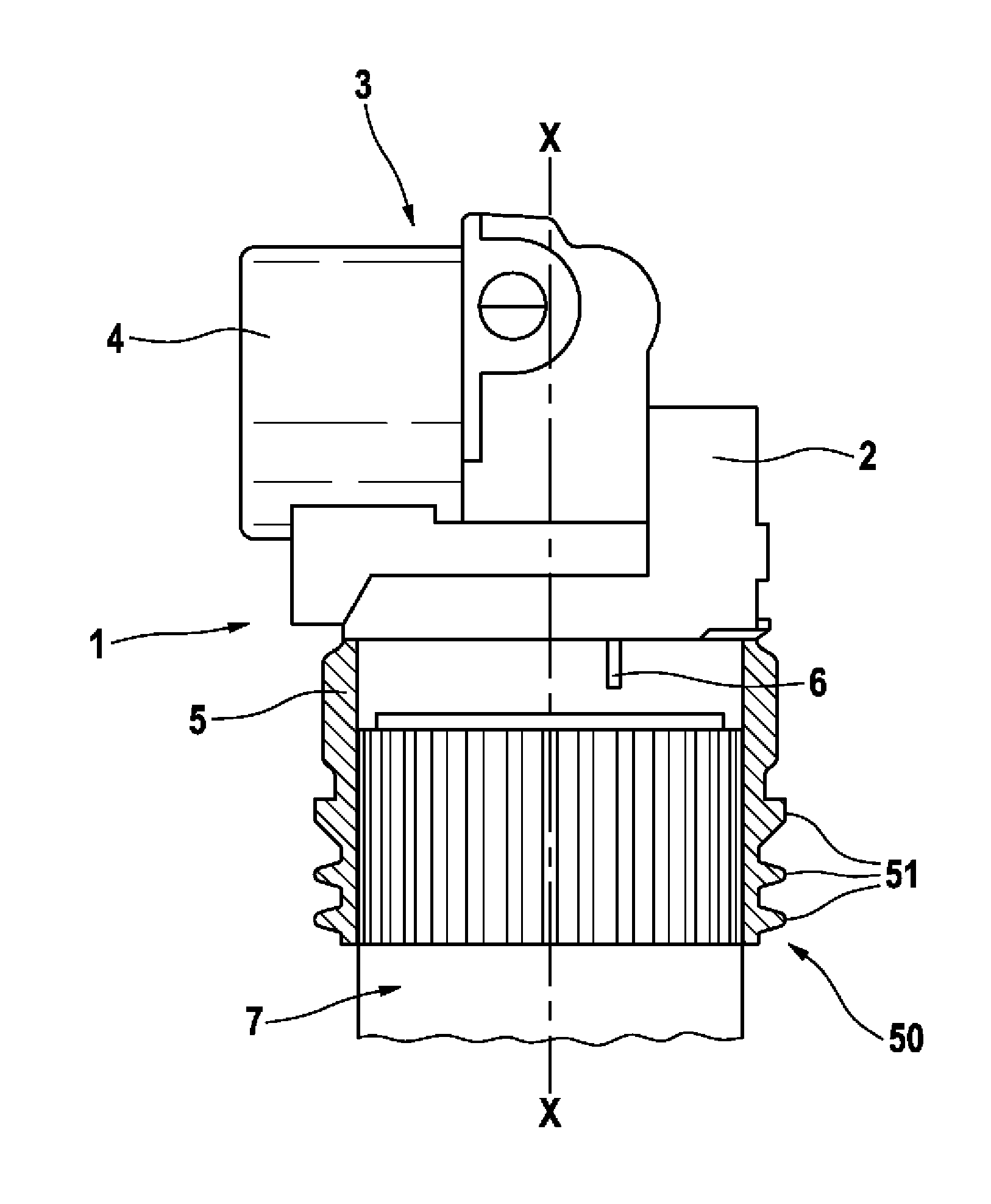
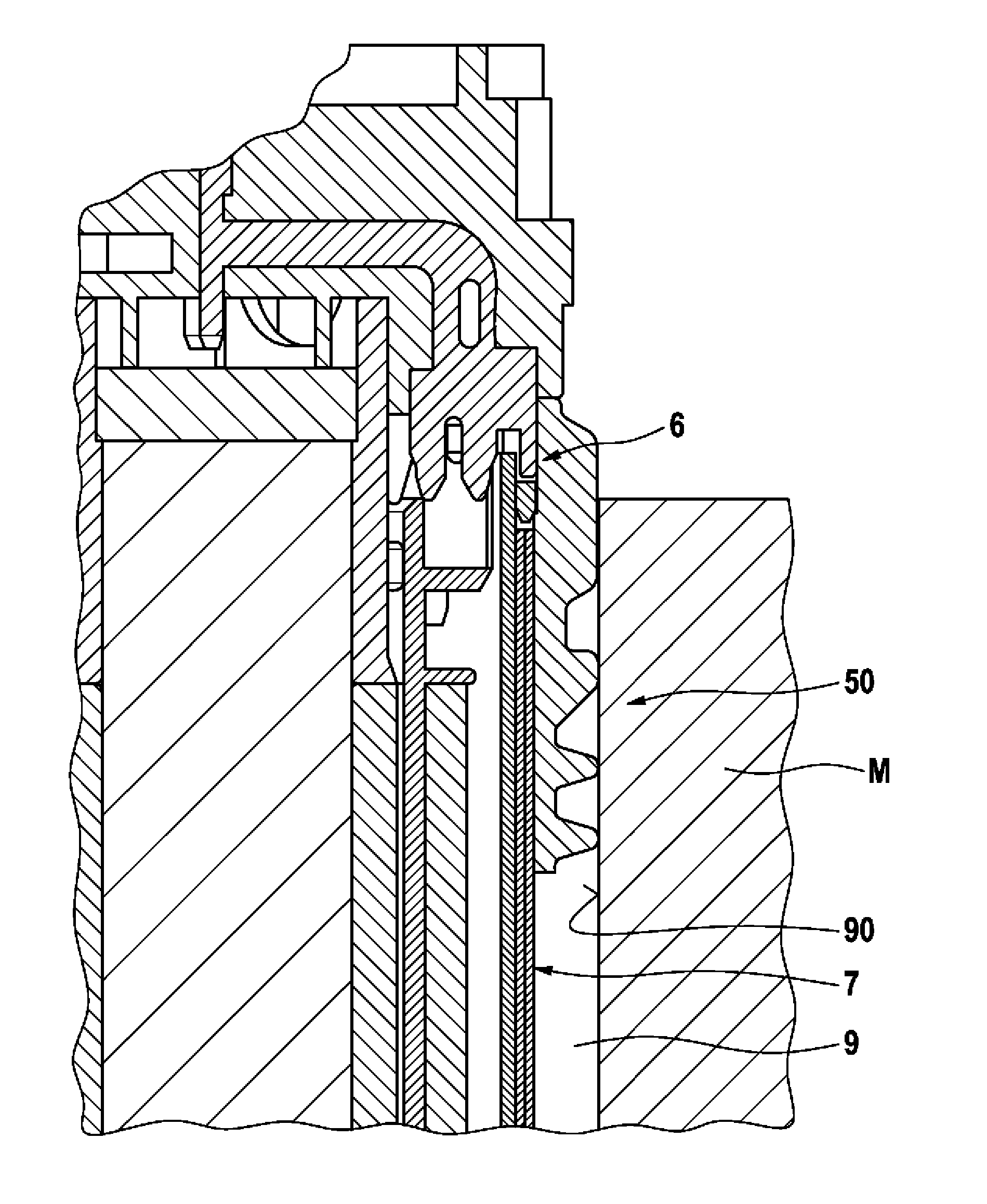
[0025] Refer below Figures 1 to 3 The ignition coil 1 and the production method based thereon are described.

[0026] exist figure 1 A section of an ignition coil 1 according to the invention is shown in , in the upper region of which a so-called ignition coil head is arranged in a housing 2 . It is used on the one hand for the electrical connection to the periphery of the ignition coil (control cable) and on the other hand for the internal electrical connection of the coil component 3 for generating the ignition spark (coil component not shown in detail). In this case, the ignition coil head includes a ground connection to the first contact region 6 , which leads to the outside. The upper edge of the connecting device 5 , which completely surrounds the housing 2 of the ignition coil 1 , is also arranged approximately on the upper edge of the first contact region 6 . The seal 50 with the sealing lip 51 connects downwards if the surface of the connecting device 5 is substan...


PUM


Abstract

The invention relates to an ignition coil for an internal combustion engine, comprising a housing (2), a coil assembly (3), a connection assembly (4) for connecting the ignition coil, and a coupling device (5) for coupling the ignition coil in a motor block (M), wherein the coupling device (5) is formed at least partially of an electrically conductive plastic composite material and is designed to connect the ignition coil to a motor block (M) in an electrically conductive manner.

Description

technical field [0001] The invention relates to an ignition coil for an internal combustion engine with means for connecting the ignition coil to an engine block and / or to a spark plug hole, and to a method for producing the ignition coil. Background technique [0002] In an internal combustion engine, an ignition coil is connected to a spark plug for igniting a combustible gas or gas mixture at a predetermined moment by means of an ignition spark. For this purpose, electrodes, usually arranged at a distance from each other, are arranged in the combustion chamber and are charged at predetermined instants with a potential difference, on the basis of which the ignition spark travels through a free path between the electrodes and thus Ignite gas or gas mixture. The junctions between the ignition coil and the engine block and / or between the ignition coil and the spark plug hole meet a number of severe conditions, which are caused not only by the operation of the internal combus...

Claims


Application Information

Patent Timeline
Patent Type & Authority Applications(China)
IPC IPC(8): H01T13/04F02P13/00H01F27/06H01F38/12
CPCH01T13/04F02P13/00H01F27/06H01F38/12
Inventor K·林登塔尔J·赫尔特尔T·格拉夫P·比希尔
Owner ROBERT BOSCH GMBH
Learn More