Reaction cavity

A technology of reaction chamber and reaction area, applied in the field of reaction chamber, to achieve the effect of reducing local low temperature, maintaining normal progress, and prolonging the diffusion path

Inactive Publication Date: 2013-08-28
光垒光电科技(上海)有限公司
View PDF6 Cites 8 Cited by
  • Summary
  • Abstract
  • Description
  • Claims
  • Application Information

AI Technical Summary

Problems solved by technology

[0006] The object of the present invention is to provide a reaction chamber to at least alleviate the problem in the prior art that the distribution of purge gas affects the uniformity of the reaction in the reaction area

Method used


Image

  • Reaction cavity
  • Reaction cavity
  • Reaction cavity

Examples


Embodiment Construction

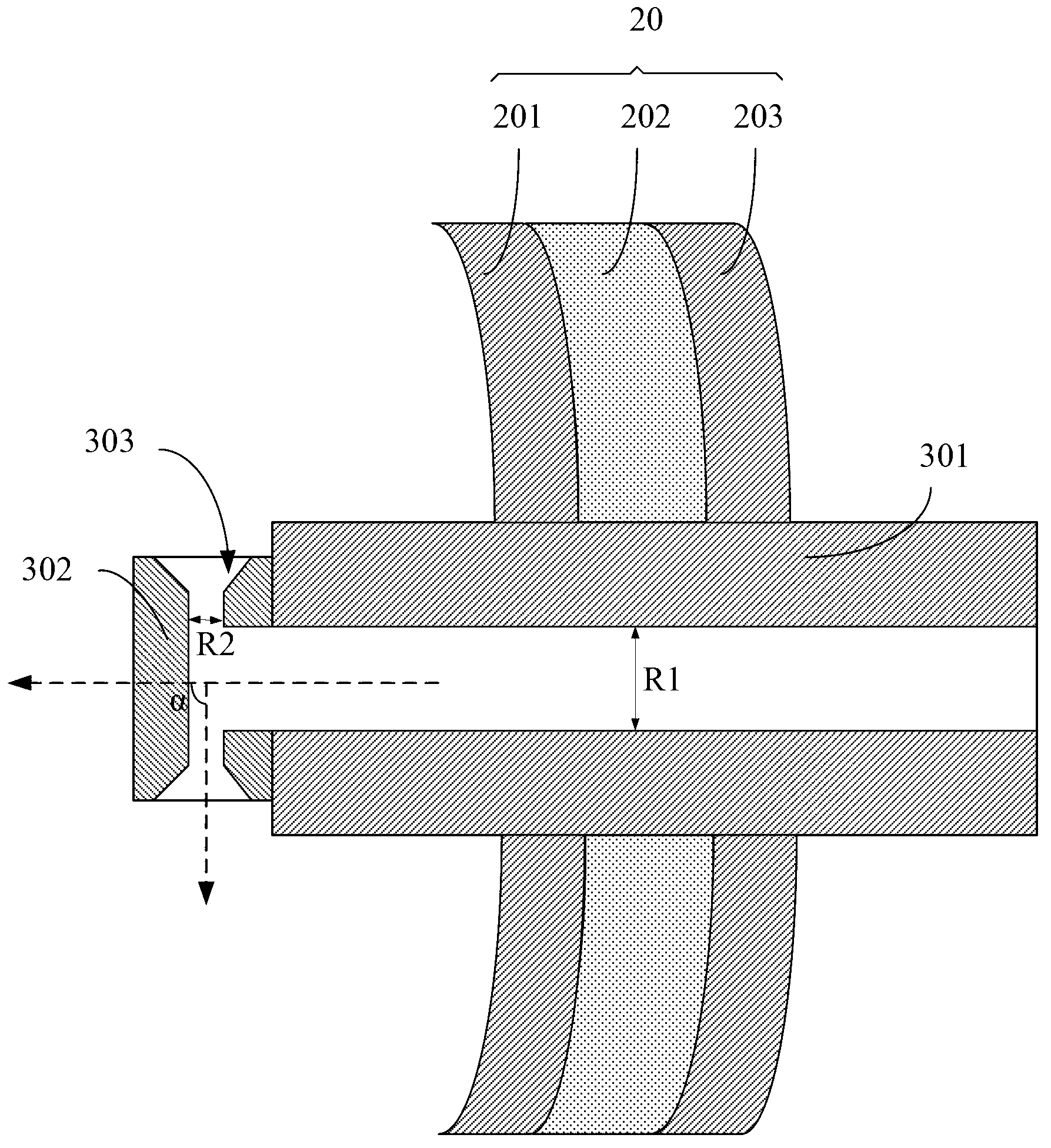
[0014] It can be seen from the content recorded in the background art that the reaction chamber of the prior art has the problem that the purging gas easily causes the local temperature of the inner lining of the chamber to be too low. The core idea of ​​the present invention is that by improving the gas outlet of the pipeline leading into the purge gas, the gas outlet direction of the purge gas can be controlled, and the gas outlet range can be expanded, so that the distribution of the purge gas can be changed, and less or avoid damage to the lining. The influence of the local temperature of the bottom.

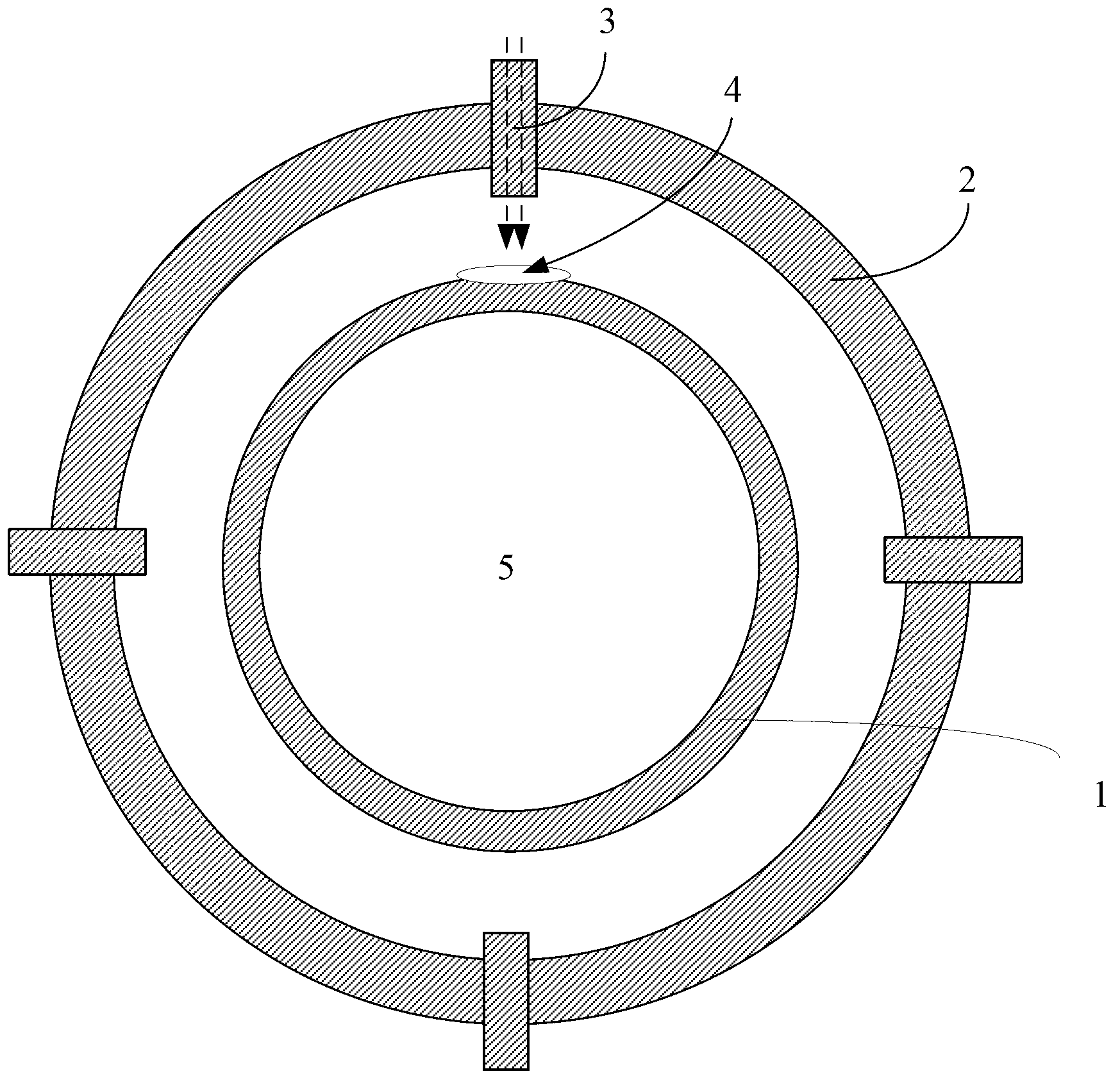
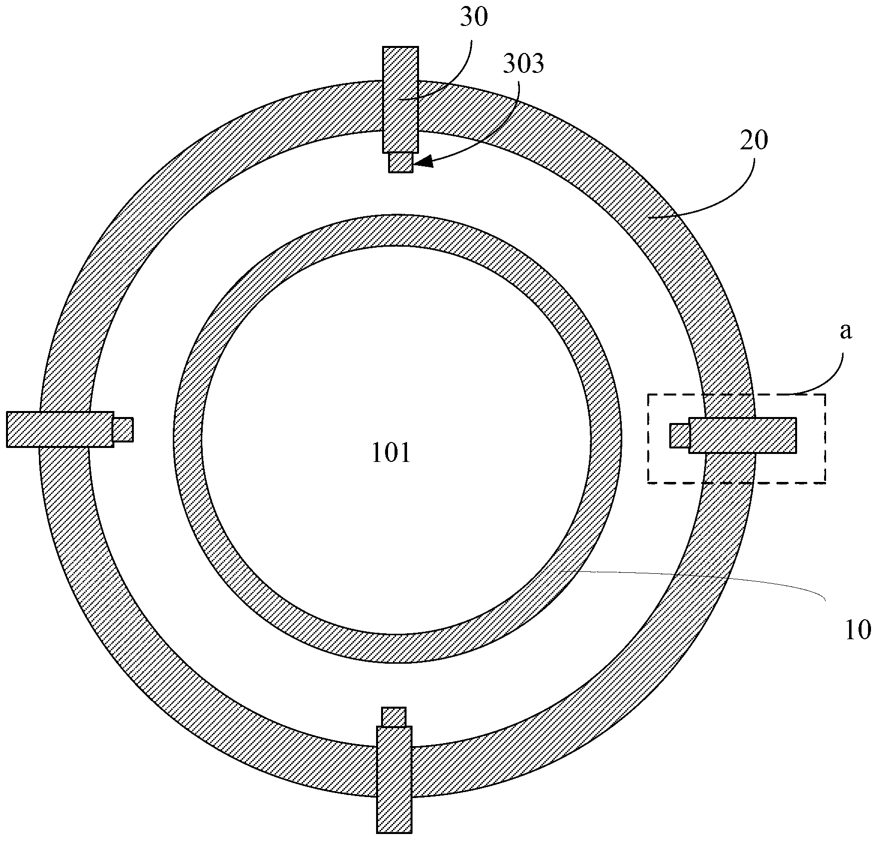
[0015] Please refer to figure 2 , an embodiment of the present invention provides a reaction chamber, including a chamber liner 10 and a cooling chamber 20, the chamber liner 10 is sleeved in the reaction chamber and surrounds the reaction region 101 of the reaction chamber, specifically, The reaction area 101 is provided with a shower head and a graphite disk (not shown) ...


PUM


Abstract

The invention discloses a reaction cavity which comprises a cavity inner liner, a cooling cavity and a purging structure, wherein the purging structure comprises a first air inlet pipe passing through the cooling cavity from the outside of the cooling cavity; the first air inlet pipe is provided with an air outlet at the end arranged towards the cavity inner liner; the direction of the connecting line from the air outlet of the first air inlet pipe to the shortest distance between the cavity inner liner and the surface of the cooling cavity is taken as the first direction; the direction in which the purge gas is guided out from the air outlet is taken as the second direction; an included angle is formed between the second direction and the first direction, so that the diffusion path of the purge gas can be prolonged, the contact area of the inner liner is enlarged, and the cooling effect is reduced; and therefore, the phenomenon of low local temperature of the cavity inner liner can be reduced, and the even airflow field can be formed. Furthermore, the space between the cavity inner liner and the inner wall of the cooling cavity is protected and maintained to be stable, so that the reaction cavity is beneficial to maintaining the reaction to be carried out normally.

Description

technical field [0001] The present invention relates to a semiconductor device, in particular to a reaction chamber which can be used at least in chemical vapor deposition. Background technique [0002] Generally, a chemical vapor deposition chamber such as an MOCVD reaction chamber includes a chamber liner and a cooling chamber. Wherein, the inner lining of the chamber is arranged in the reaction chamber and surrounds the reaction area of ​​the reaction chamber, and the cooling chamber surrounds the inner lining of the chamber so as to isolate the outside. [0003] During the reaction, the reaction area inside the chamber lining is in a high-temperature environment to provide the required reaction environment. In addition, please refer to figure 1 In the prior art, a plurality of gas pipes 3 are arranged in multiple positions around the cooling cavity 2, and the area between the cooling cavity 2 and the cavity liner 1 is blown into in the radial direction of the cooling ca...

Claims


Application Information

Patent Timeline
Patent Type & Authority Applications(China)
IPC IPC(8): C23C16/44C23C16/455
Inventor 仁君谭华强
Owner 光垒光电科技(上海)有限公司
Why Eureka
Try Eureka