Ultra-thin electromagnetic wave converging and diverging lens design method based on phase discontinuous surface

A technology of divergent lens and design method, which is applied in the field of electromagnetics, can solve the problem of lens thickness limit, etc., and achieve the effect of small structure size, high transmittance, and thin thickness

Inactive Publication Date: 2013-08-28
HARBIN INST OF TECH
View PDF3 Cites 10 Cited by
  • Summary
  • Abstract
  • Description
  • Claims
  • Application Information

AI Technical Summary

Problems solved by technology

[0005] The purpose of the present invention is to solve the problem of the thickness limit of the traditional lens, and pr...

Method used


Image

  • Ultra-thin electromagnetic wave converging and diverging lens design method based on phase discontinuous surface
  • Ultra-thin electromagnetic wave converging and diverging lens design method based on phase discontinuous surface
  • Ultra-thin electromagnetic wave converging and diverging lens design method based on phase discontinuous surface

Examples


specific Embodiment approach 1

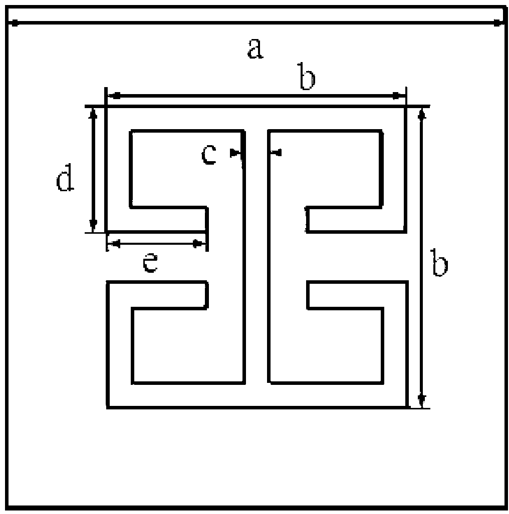
[0021] Specific implementation mode one: the following combination figure 1 Describe this embodiment, the design method of the ultra-thin electromagnetic wave converging and diverging lens based on the phase discontinuous surface described in this embodiment, the design method is:

[0022] Step 1. First, set the f of the lens to be made, where f is the focal length of the focus point;

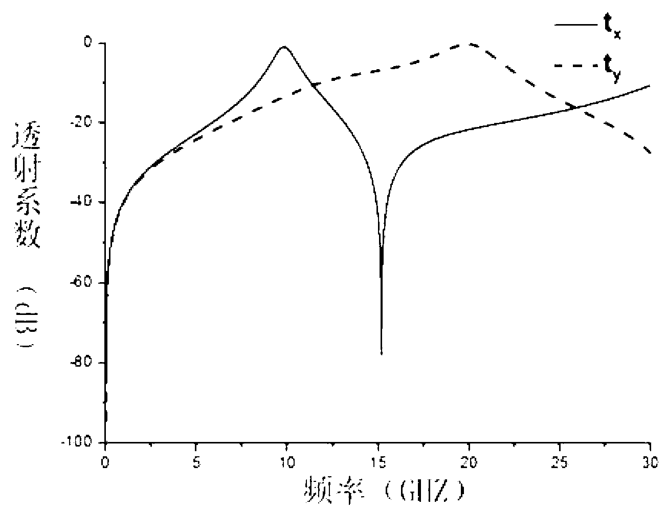
[0023] Step 2. According to the principle of the Pancharatnam–Berry phase device, for a unit structure with a side length a=5mm, the electric field is polarized along the X-axis and Y-axis of the unit structure for vertically incident electromagnetic waves, then the transmission coefficient of the unit structure is t x and t y , the first-order resonance frequency point is 9.81GHz, at the first-order resonance frequency point, the transmission coefficient t x =1,t y =0, for the transmitted component with the opposite hand direction to the incident circularly polarized wave, a phase shift rel...

specific Embodiment approach 2

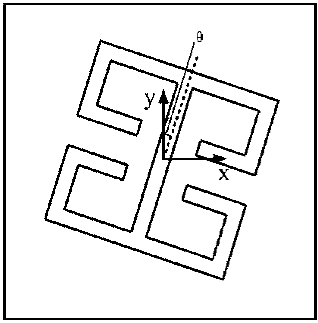
[0029] Specific implementation mode two: the following combination figure 1 Describe this embodiment, this embodiment will further explain Embodiment 1, the principle of the Pancharatnam-Berry phase device described in step 2 of this embodiment refers to: introducing an arbitrary phase to the opposite handedness transmission component of the incident circularly polarized wave For a left-handed or right-handed circularly polarized vertically incident wave, after each unit structure rotates θ around its axis, its transmission field is expressed as:

[0030]

[0031] in η E = | 1 2 ( t x + t y e iφ ) | ...


PUM


Abstract

The invention discloses an ultra-thin electromagnetic wave converging and diverging lens design method based on a phase discontinuous surface and belongs to the field of electromagnetism. The ultra-thin electromagnetic wave converging and diverging lens design method based on the phase discontinuous surface solves the problem that a traditional lens is limited in thickness. The design method includes the following steps that first, the focal distance of a required focus point is set; second, according to the principle of a Pancharatnam-Berry phase device, for vertical incidence electromagnetic waves with the electric field polarized along the X-axis and the Y-axis, the first-stage resonance frequency point of a unit structure with the length of a side equal to 5mm is 9.81GHz, and any dispersed phase shift can be introduced to transmitted electromagnetic waves; third, according to the required phase distribution of the converging and diverging lens, an expression of the relation between the angle theta by which each unit rotates in the positive direction of the X-axis and the distance x from the unit to the original point can be obtained on the first-stage resonance frequency point; fourth, f in the first step is put into the first formula in the third step, and thus design parameters of the lens are obtained, and the ultra-thin electromagnetic wave converging and diverging lens design based on the phase discontinuous surface is completed. The ultra-thin electromagnetic wave converging and diverging lens design method based on the phase discontinuous surface is applicable to the field of designing and machining of electromagnetic wave regulation and control lenses.

Description

technical field [0001] The invention relates to a lens design method, which belongs to the field of electromagnetism. Background technique [0002] As a commonly used electromagnetic wave artificial control device, the lens is widely used in microwave systems and optical systems. Because lenses can change the propagation direction and spatial distribution of electromagnetic waves to a certain extent, lenses have important application values ​​in multi-beam antennas, satellite communications, radar measurement calibration, electronic countermeasures, millimeter waves, and optical imaging systems. The imaging mechanism of the above lens is still based on the traditional law of refraction, that is, electromagnetic waves form a phase difference through phase accumulation along the propagation path in the lens, and then form a specific refraction effect. [0003] However, the lens based on this mechanism has the following defects: 1. The limitation of lens thickness. First, for...

Claims


Application Information

Patent Timeline
IPC IPC(8): H01Q15/02
Inventor 吴群丁旭旻张狂王二超
Owner HARBIN INST OF TECH
Why Eureka
Try Eureka