
Rolling bearing cages and rolling bearings

A technology of rolling bearings and cages, applied in the field of rolling bearings, can solve problems such as non-uniformity, expensive construction, and complexity, and achieve the effects of avoiding collisions, improving service life, and simplifying assembly

Inactive Publication Date: 2016-11-09
SCHAEFFLER TECH AG & CO KG
View PDF9 Cites 0 Cited by
  • Summary
  • Abstract
  • Description
  • Claims
  • Application Information

AI Technical Summary

Problems solved by technology

The disadvantage of the solution of DE 102 46 825 A1 is that by imposing the required gap due to the different materials of the segments and of the bearing rings, mutual collisions cannot be avoided in principle and the segments are distributed non-uniformly and uncontrollably during operation on the circumference
The disadvantage of the solution according to DE 10 2009 014 779 A1 is that the use of metal spring elements in combination with tension-bearing coupling elements that mechanically connect the segments results in a complex and expensive construction and that the individual segments cannot be completely avoided. collide with each other

Method used


Image

  • Rolling bearing cages and rolling bearings
  • Rolling bearing cages and rolling bearings
  • Rolling bearing cages and rolling bearings

Examples


Embodiment Construction

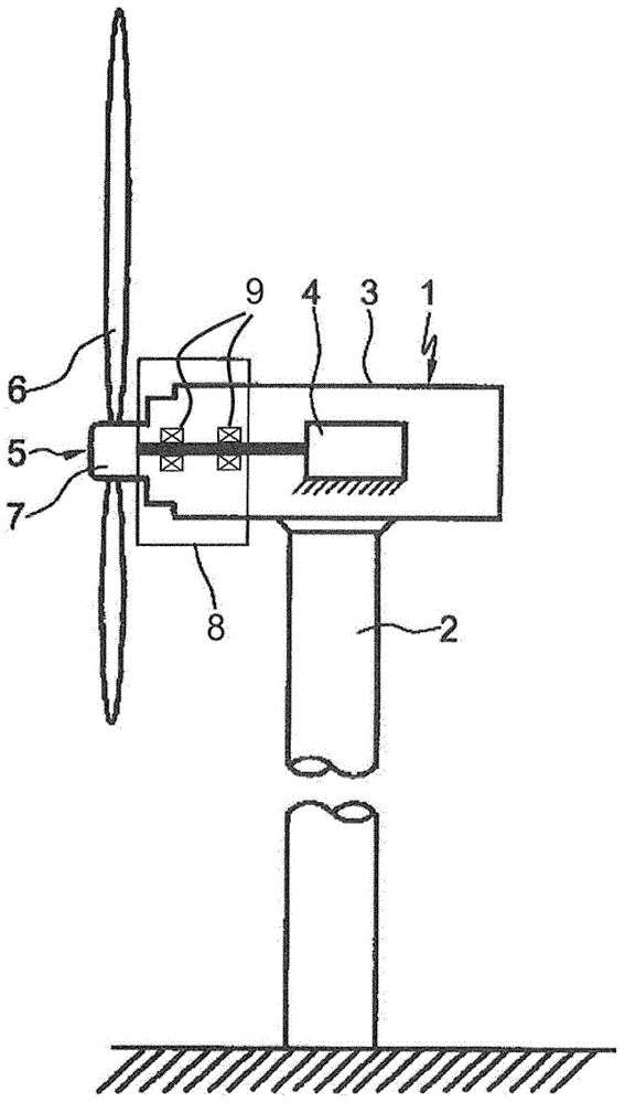
[0032] figure 1 A wind power plant 1 is shown which comprises a rotor mounting by means of two rolling bearings according to the invention. The wind power plant 1 comprises a machine tower 2 on which a nacelle 3 with a generator 4 and a wind-driven rotor 5 having a rotor hub 7 carrying a plurality of rotor blades 6 is arranged. The rotor 5 is carried by a rotor bearing 8 . The rotor bearing 8 comprises two rolling bearings 9 according to the invention, for example two tapered roller bearings in an O-arrangement.

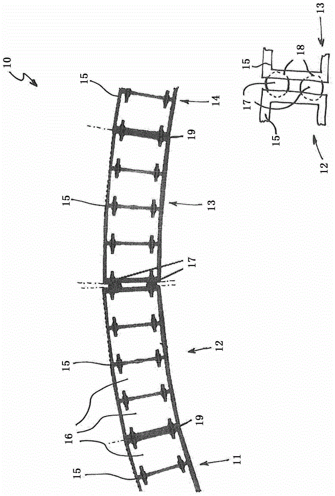
[0033] figure 2 A first embodiment of a rolling bearing cage 10 according to the invention is shown. The rolling bearing cage is designed as a rolling bearing cage 10 of a tapered roller bearing and is partially shown in a schematic plan view.

[0034] The rolling bearing cage 10 comprises a plurality of segments arranged loosely in the circumferential direction, of which four segments 11 , 12 , 13 , 14 are (partially) shown. Each segment 11 , 12 , 13 , 14 has ...


PUM

PropertyMeasurementUnit
diameteraaaaaaaaaa

Abstract

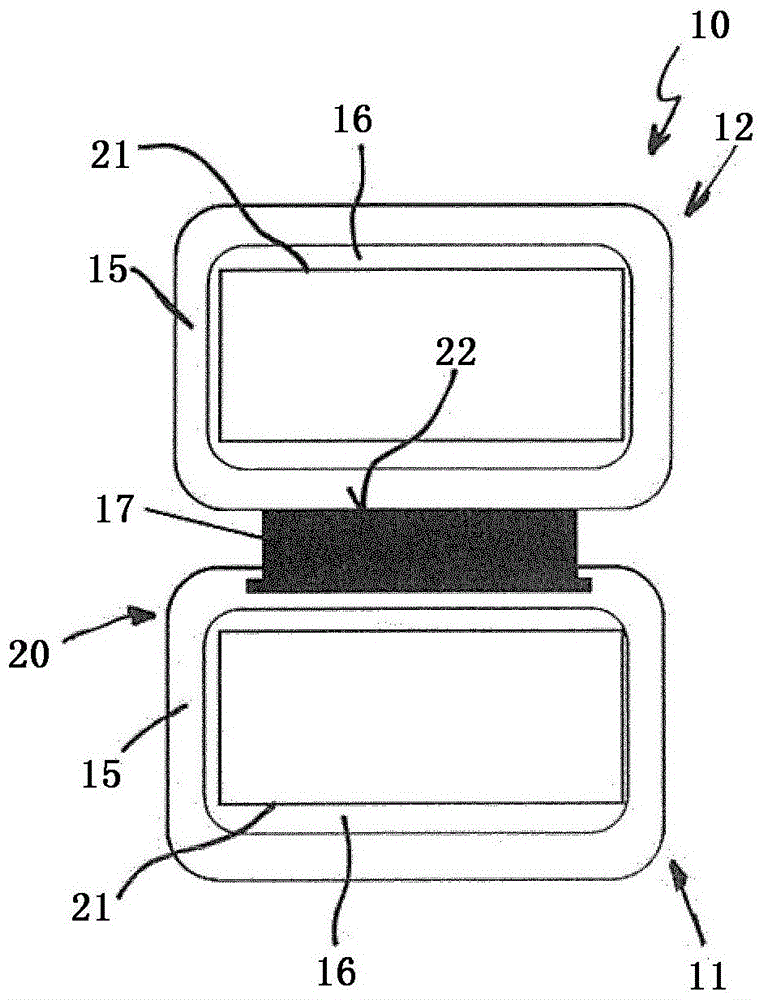
The invention relates to a rolling bearing cage (10) having a plurality of loose segments (11, 12, 13, 14) arranged in the circumferential direction, wherein the segments (11, 12, 13, 14 ) has a base body (15) with at least one pocket (16) for receiving a rolling element (21). According to the invention it is provided that at least one play compensating element ( 17 ) is arranged between two adjacent base bodies ( 15 ) in the circumferential direction and that the play compensating element ( 17 ) has a higher elasticity in the circumferential direction than the base bodies ( 15 ) And the segments ( 11 , 12 , 13 , 14 ) are arranged without gaps in the circumferential direction at room temperature. The invention also relates to a rolling bearing comprising such a rolling bearing cage.

Description

technical field [0001] The invention relates to a rolling bearing cage having a plurality of loose segments arranged in the circumferential direction, wherein the segments have a base body with at least one pocket for receiving rolling bodies. The invention also relates to a rolling bearing comprising such a rolling bearing cage. Background technique [0002] Such rolling bearing cages are particularly suitable for use in so-called large rolling bearings. Large roller bearings are used, for example, in rotor bearings of wind power plants or in main bearings of tunnel boring machines and have a pitch circle diameter of greater than 600 mm, for example greater than 1000 mm or greater than 1500 mm. [0003] In large rolling bearings, however, conventional rolling bearing cages consisting of two side disks and a plurality of transverse webs connecting the side disks can also be used. However, the manufacture and assembly of such a rolling bearing cage becomes difficult as the ...

Claims


Application Information

Patent Timeline
Patent Type & Authority Patents(China)
IPC IPC(8): F16C25/08F16C33/38F16C33/51
CPCF16C25/08F16C33/513F16C2300/14F16C2360/31F16C2208/10F16C33/6648F16C33/56F16C33/46F16C33/6637F16C33/664
Inventor 安德烈亚斯·曼戈尔德托比亚斯·穆勒安德烈亚斯·比尔莱恩
Owner SCHAEFFLER TECH AG & CO KG
Learn More