Motor control device

A motor control and motor technology, applied in the direction of program control, damping device, control system, etc., can solve problems such as insufficient vibration suppression

Active Publication Date: 2013-08-28
MITSUBISHI ELECTRIC CORP
View PDF5 Cites 16 Cited by
  • Summary
  • Abstract
  • Description
  • Claims
  • Application Information

AI Technical Summary

Problems solved by technology

However, there is a problem that the vibration suppression effect may not be sufficiently obtained even if the parameter (gain constant) is changed while accurately corresponding to the changed mechanical natural frequency.

Method used


Image

  • Motor control device
  • Motor control device
  • Motor control device

Examples


Embodiment approach 1

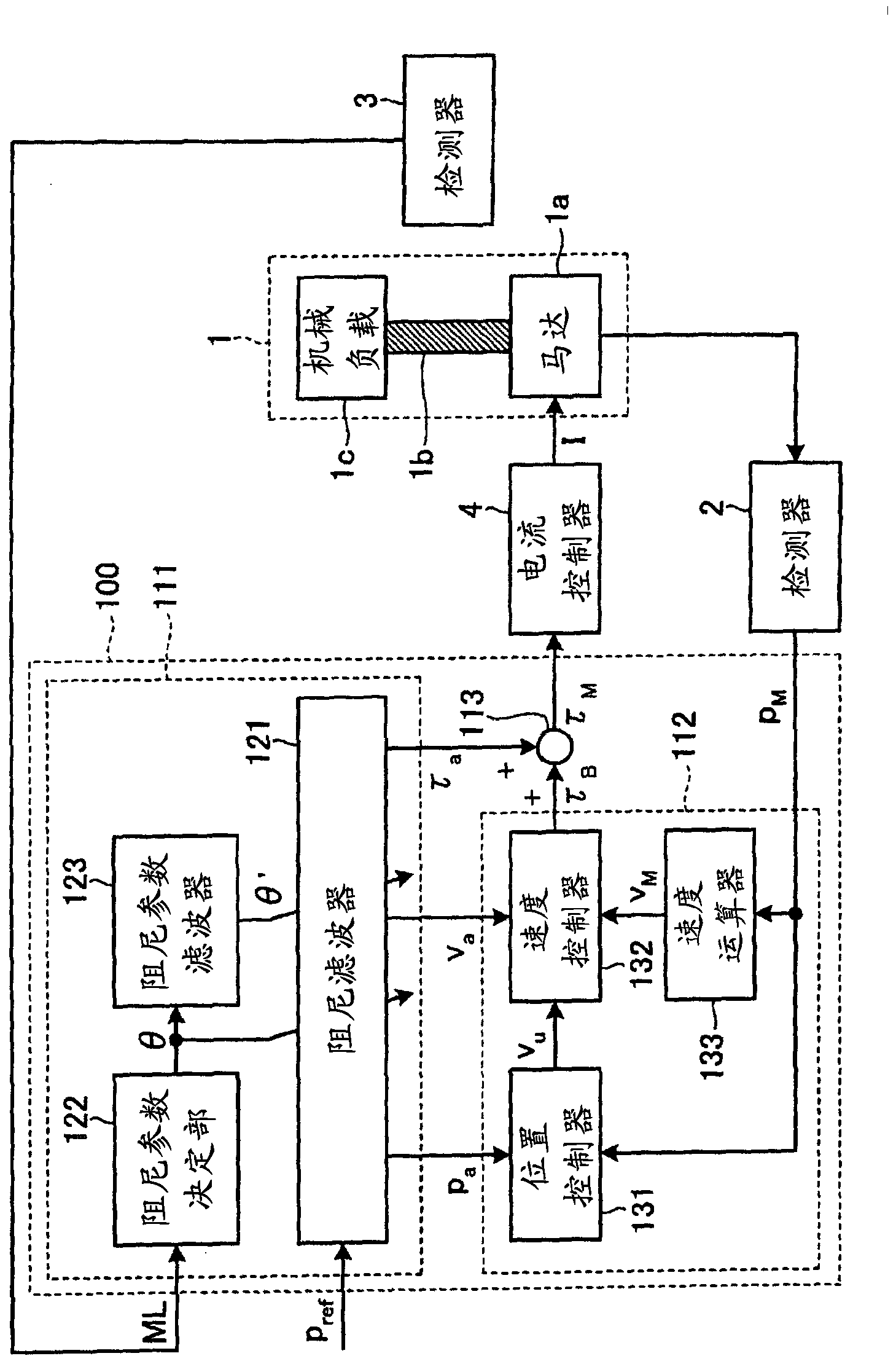
[0028] use figure 1 The configuration of the motor control device 100 according to Embodiment 1 will be described. figure 1 It is a block diagram showing the configuration of the motor control device 100 according to the first embodiment.

[0029] The motor control device 100 receives from the outside (for example, a host controller not shown) an operation target value (position command) pref indicating a position target value of the driven control object 1 , and receives from the detector 2 ( For example, the motor operation detection value p detected by an encoder) indicating the position of the motor 1a (for example, the rotational position of the rotor inside the motor 1a or the driving position of the movable element) M . In addition, the motor control device 100 receives a parameter change signal (state information) ML indicating the state of the controlled object 1 related to the vibration characteristics of the controlled object 1 from the detector 3 . The motor con...

Embodiment approach 2

[0119] Next, the motor control device 200 according to Embodiment 2 will be described. Hereinafter, description will focus on points different from Embodiment 1. FIG.

[0120] The difference between the motor control device 200 of the present embodiment and the motor control device 100 of the first embodiment lies in the content of processing in the damping filter (calculation method of model position, model velocity, and model torque). That is, at the resonant frequency ω p and anti-resonance frequency ω z Roughly equal (ω p ≈ω z ) case, generate the target value p from the action ref The motion compensation signal (model position p a ), perform the first-order differential and second-order differential of the generated motion compensation signal to calculate the model velocity v a , model torque τ a .

[0121] Specifically, the motor control device 200 has Figure 7 The feedforward control unit 211 as shown. Figure 7 It is a block diagram showing the internal conf...

Embodiment approach 3

[0144] Next, a motor control device 300 according to Embodiment 3 will be described. Hereinafter, description will focus on points different from Embodiment 1. FIG.

[0145] The difference between the motor control device 300 of the present embodiment and the motor control device 100 of the first embodiment lies in the content of processing in the damping filter (calculation method of model position, model velocity, and model torque). That is, even at the resonant frequency ω of the controlled object 1 p , anti-resonance frequency ω z In different cases, the target value p from the action is still generated ref The motion compensation signal (model position p a , Resonant frequency compensation signal p cp ), for the generated motion compensation signal (model position p a ) to calculate the model velocity v a , and the action compensation signal (resonant frequency compensation signal p cp ) to calculate the model torque τ a .

[0146] Specifically, the motor control...


PUM


Abstract

A motor control device controls operation of a control object that has a motor and an oscillatable element. The motor control device comprises: a generation unit that generates, in accordance with status information that relates to the oscillation characteristics of the control object and that indicates the status of the control object, a first parameter that indicates the oscillation characteristics of the control object; a first calculation unit that calculates a second parameter in accordance with the time change amount of the first parameter generated by the generation unit; a second calculation unit that calculates a model torque using an operation target value, the first parameter, and the second parameter so that the control subject does not excite oscillation; and an issuance unit that causes a torque instruction to be issued in accordance with the model torque computed by the second calculation unit.

Description

technical field [0001] The present invention relates to motor control devices. Background technique [0002] In an industrial machine with low rigidity, if the positioning drive of the industrial machine is performed by a motor, residual vibration may occur at the time of stop due to machine resonance or the like. In order to suppress such residual vibration, the motor control device that operates the industrial machinery through the motor calculates the control signal based on the operation target value so that the signal component of the vibration frequency (resonance frequency) of the industrial machinery is reduced, and performs industrial Damping control with mechanical devices. In order to perform this damping control, the motor control device needs damping parameters for damping control corresponding to the vibration frequency of the control system including the industrial machinery. For an industrial machine whose vibration frequency does not change during operatio...

Claims


Application Information

Patent Timeline
Patent Type & Authority Applications(China)
IPC IPC(8): H02P29/00G05D19/02
CPCH02P23/0004B25J9/1641G05B2219/39186G05B2219/39195G05B2219/41128G05B2219/41166G05B2219/41233G05B2219/42077H02P29/50G05B5/01
Inventor 五十岚裕司池田英俊竹居宽人
Owner MITSUBISHI ELECTRIC CORP
Why Eureka
Try Eureka