Liquid distribution and redistribution device for multistage rotating rectification bed

A technology of liquid distributor and liquid distribution, which is applied in the direction of fractionation and so on

Active Publication Date: 2013-09-04
ZHONGBEI UNIV
View PDF4 Cites 10 Cited by
  • Summary
  • Abstract
  • Description
  • Claims
  • Application Information

AI Technical Summary

Problems solved by technology

[0006] The present invention is to solve the problem of liquid distribution in the counter-current rotating packed bed, and proposes a tubular and conical liquid distributor with static liquid distribution and Liquid distributor and redistributor for multi-stage rotary rectification bed composed of dynamic U-shaped and disk-type liquid distributor

Method used


Image

  • Liquid distribution and redistribution device for multistage rotating rectification bed
  • Liquid distribution and redistribution device for multistage rotating rectification bed
  • Liquid distribution and redistribution device for multistage rotating rectification bed

Examples


Embodiment Construction

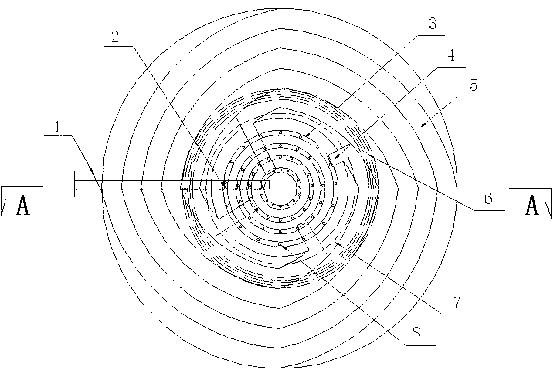
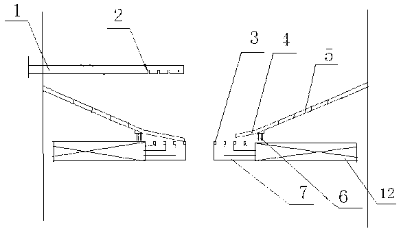
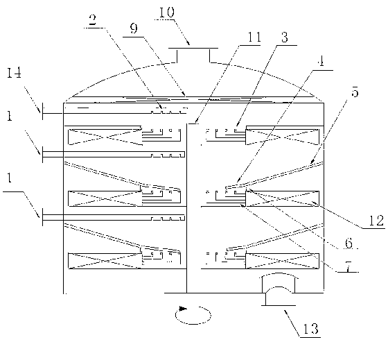
[0023] There are 4 liquid distribution grooves 2 on the front end of the inlet pipe 1, 4 spiral grooves 5 on the cone -shaped liquid and distributer 4, and the U -shaped flat -rotating liquid distributor 7 structure includes a flat disk, a flat plate ringThere are U -shaped split grooves 3 on the inner wall of the shape, the bottom of the U -shaped split groove is equipped with a cloth liquid hole 8, the U -shaped flat plate rotating liquid distributor 7 is 4, and it is concentric.Large, from bottom to top arrangement settings.

[0024] The position of the 4 liquid distribution groove 2 is corresponding to the position of the 4 U -shaped flat plate rotating liquid distributor 7.The outer side of the liquid and distributer 4 is connected with the cylindrical of the cylinder of the rotating filler.There is a maze -type seal 6 in the lower side of the cone -shaped liquid and distributer 4.

[0025] In this way, there are 4 long cloth grooves 2 drooping in the horizontal liquid pipe 1...


PUM


Abstract

The invention relates to a multistage counter-current rotating rectification bed and especially relates to a liquid distribution and redistribution device for a multistage rotating rectification bed. The multistage counter-current rotating rectification bed solves the problem of distribution of a liquid in a counter-current rotating packed bed, and is composed of tubular and tapered liquid distributors having static liquid distribution effects and dynamic U-shaped and disc-type liquid distributors. The liquid distribution and redistribution device comprises a liquid inlet pipe, a tapered liquid-receiving and distribution device, and U-shaped flat-disc rotating liquid distributor. The liquid distribution and redistribution device is used for a single-stage or multistage counter-current rotating packed bed and can reinforce a gas-liquid transmission process and improve transmission efficiency.

Description

Technical field [0001] The present invention involves a multi -level reverse rotating spiny bed, which is specifically distributed and re -distributed for a multi -level rotating refractory bed. Background technique [0002] Rotating the distillation tool is a new type of device that uses a centrifugal force that uses the rotation of the filler to strengthen the heat transfer process.Widely used in the recycling of solvents and product purification of petroleum, chemical, pharmaceutical, and explosives.It has been proved by experiments and practice that the rotating filling bed can increase the heat transfer coefficient of 1-2 in magnitude, and the equipment volume is 70 times. It is the transistor of the chemical industry in the 21st century.At present, most of the single -level rotating filler beds with different structures are restricted in the processing volume and separation effects. Multi -level rotating filler beds are the development direction of industrialization. [000...

Claims


Application Information

Patent Timeline
Patent Type & Authority Applications(China)
IPC IPC(8): B01D3/30
Inventor 刘有智栗秀萍申红艳袁志国张巧玲祁贵生焦纬洲
Owner ZHONGBEI UNIV
Why Eureka
Try Eureka