
Deactivated catalyst regeneration and density grading system and process thereof

A technology for deactivating catalysts and density classification, which is applied in catalyst regeneration/reactivation, physical/chemical process catalysts, chemical instruments and methods, etc., and can solve the problem of inability to remove heavy metal impurities at the same time.

Active Publication Date: 2013-09-04
CHNA ENERGY INVESTMENT CORP LTD +1
View PDF7 Cites 8 Cited by
  • Summary
  • Abstract
  • Description
  • Claims
  • Application Information

AI Technical Summary

Problems solved by technology

[0011] Although the methods disclosed in the above-mentioned prior art relate to the regeneration of deactivated catalysts and the density classification of spent catalysts, they cannot remove various impurities, such as carbon-containing impurities, sulfur-containing impurities and Heavy metal impurities are removed at the same time

Method used


Image

  • Deactivated catalyst regeneration and density grading system and process thereof
  • Deactivated catalyst regeneration and density grading system and process thereof
  • Deactivated catalyst regeneration and density grading system and process thereof

Examples


Embodiment 1

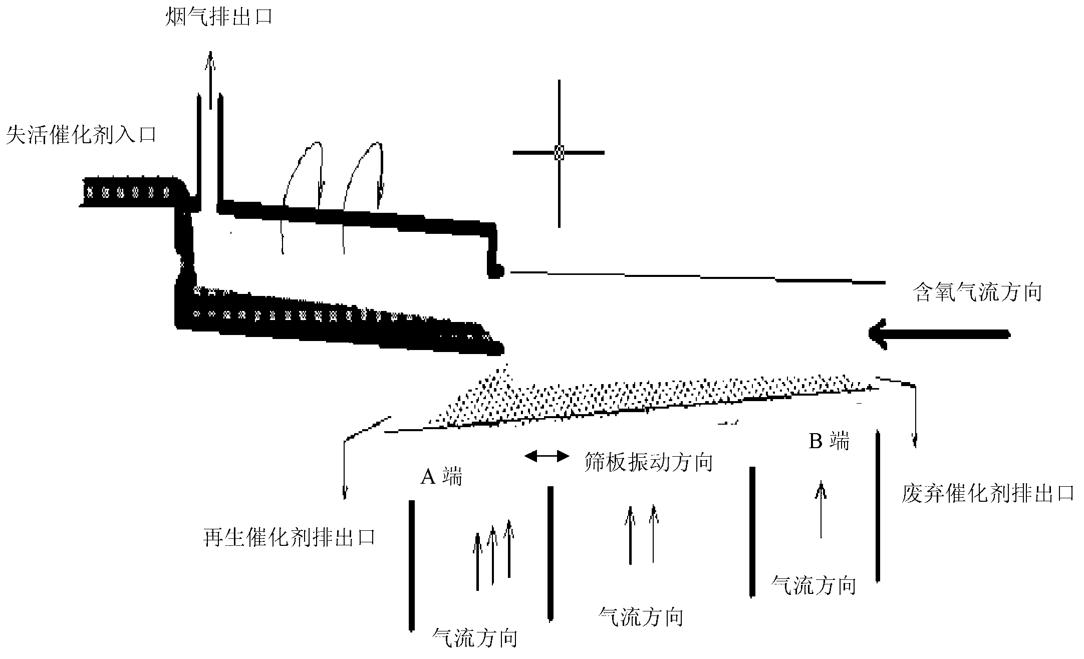
[0060] according to figure 1 The process shown is to regenerate and classify the deactivated catalyst after deoiling.

[0061] After the above-mentioned deoiled deactivated catalyst particles are screened with a sieve, they are sent to the rotary kiln for desulfurization and carbon removal regeneration through a hopper. With the rotation of the rotary kiln, the deactivated catalyst is spread on the surface On the inner surface, the thickness of the catalyst is maintained between 0.5-1.0 cm when the rotary kiln rotates, and the process air (oxygen-containing flow) is reversely passed into the rotary kiln, and the process air / catalyst volume in which the desulfurization and carbon removal reactions occur in the rotary kiln The ratio (air / agent ratio) was 4000 / hour, and the oxygen content in the process air was 21% by volume.

[0062] Control the temperature rise of the rotary kiln within 10°C / min to carry out the slow regenerative coking process. The final coking temperature (m...

Embodiment 2

[0069] The procedure of Example 1 was repeated under the same conditions as in Example 1 except for adjusting the following operating conditions of the vibrating sieve.

[0070] Change the inclination angle of the sieve plate from 5° to 3°; change the opening ratio of the sieve plate from 40% to 35%; change the vibration frequency from 80 times / min to 90 times / min; change the amplitude from 2 mm to 3 mm.

[0071] Likewise, the above-mentioned low-density catalyst particles collected or discharged from the lower end (A end) of the sieve plate are used as regenerated catalyst to be recycled, which is marked as regenerated catalyst C.

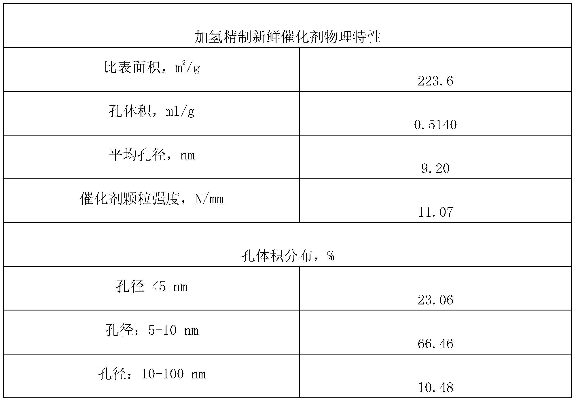
[0072] The properties of the above-mentioned regenerated catalyst C to be recycled are shown in Table 3, the process conditions for evaluating the catalytic activity of its hydrofining reaction are shown in Table 4, and the performance data of the crude oil directly liquefied from coal produced by using it are shown in Table 5.


PUM


Abstract

The invention discloses a deactivated catalyst regeneration and density grading system which comprises a rotary kiln used as a deactivated catalyst regenerator and a vibrating screen used as a density grading device of a regenerated catalyst, wherein the rotary kiln inclines horizontally for 1-3 degrees; the vibrating screen inclines horizontally for 3-5 degrees and vibrates in an inclined direction; a deactivated catalyst is regenerated in the rotary kiln, and regenerated catalyst granuless are fluidified on the vibrating screen by means of air flows penetrating through meshes of the vibrating screen from bottom to top; and under the joint action of gravity, fluidifying force and vibratory force, the regenerated catalyst granules with different densities are separated or graded on the vibrating screen.

Description

technical field [0001] The invention relates to a deactivated catalyst regeneration and density grading system and its process, in particular to a de-oiled coal direct liquefaction crude oil hydrogenation deactivated catalyst regeneration and density grading system and its process. Background technique [0002] Coal direct liquefaction is a process in which coal is converted into liquid fuels and other chemicals through hydrogenation under certain conditions such as temperature and pressure and the action of a catalyst. It is an important clean coal utilization technology. [0003] At present, more mature coal direct liquefaction processes include American H-Coal process, two-stage catalytic liquefaction process, solvent refining coal process, kerosene co-refining process, German direct liquefaction process, Japanese NEDOL process and Shenhua coal direct liquefaction process, etc. In the various coal direct liquefaction processes mentioned above, various catalysts for the di...

Claims


Application Information

Patent Timeline
IPC IPC(8): B01J38/72
Inventor 马辉郭治金环年胡云剑石玉林
Owner CHNA ENERGY INVESTMENT CORP LTD
Learn More