
Plasma enhanced chemical vapor deposition (PECVD) device

A vapor chamber and reaction chamber technology, applied in gaseous chemical plating, metal material coating process, coating, etc., can solve the problems of bulky devices, inconvenient operation for maintenance personnel, and small gaps between them

Active Publication Date: 2013-09-04
SOUTH UNIVERSITY OF SCIENCE AND TECHNOLOGY OF CHINA
View PDF3 Cites 11 Cited by
  • Summary
  • Abstract
  • Description
  • Claims
  • Application Information

AI Technical Summary

Problems solved by technology

[0003] PECVD equipment in the existing mainstream technology has the following problems: 1) When it is used to prepare thin films on large-area substrates, the gas enters from one side of the reaction chamber and is drawn out from the other side, so the uniformity of the gas flow is very poor; 2) The reaction chamber can Separate heating is used, but due to the stacked arrangement of multiple reaction chambers, the temperature of the top process reaction chamber is bound to be higher than that of the bottom reaction chamber, resulting in poor temperature consistency among the reaction chambers; 3) The reaction chambers are fixed separately On the inner wall of the vacuum chamber, the gap between each other is very small, which makes the later maintenance complicated, time-consuming and difficult; 4) Multiple reaction chambers are arranged in the same vacuum chamber, resulting in the whole device being very heavy and sometimes weighing several tons. It is very inconvenient for post-maintenance and maintenance personnel to operate, and there are potential safety hazards

Method used


Image

  • Plasma enhanced chemical vapor deposition (PECVD) device
  • Plasma enhanced chemical vapor deposition (PECVD) device
  • Plasma enhanced chemical vapor deposition (PECVD) device

Examples


Embodiment Construction

[0023] The following will clearly and completely describe the technical solutions in the embodiments of the present invention with reference to the drawings in the embodiments of the present invention.

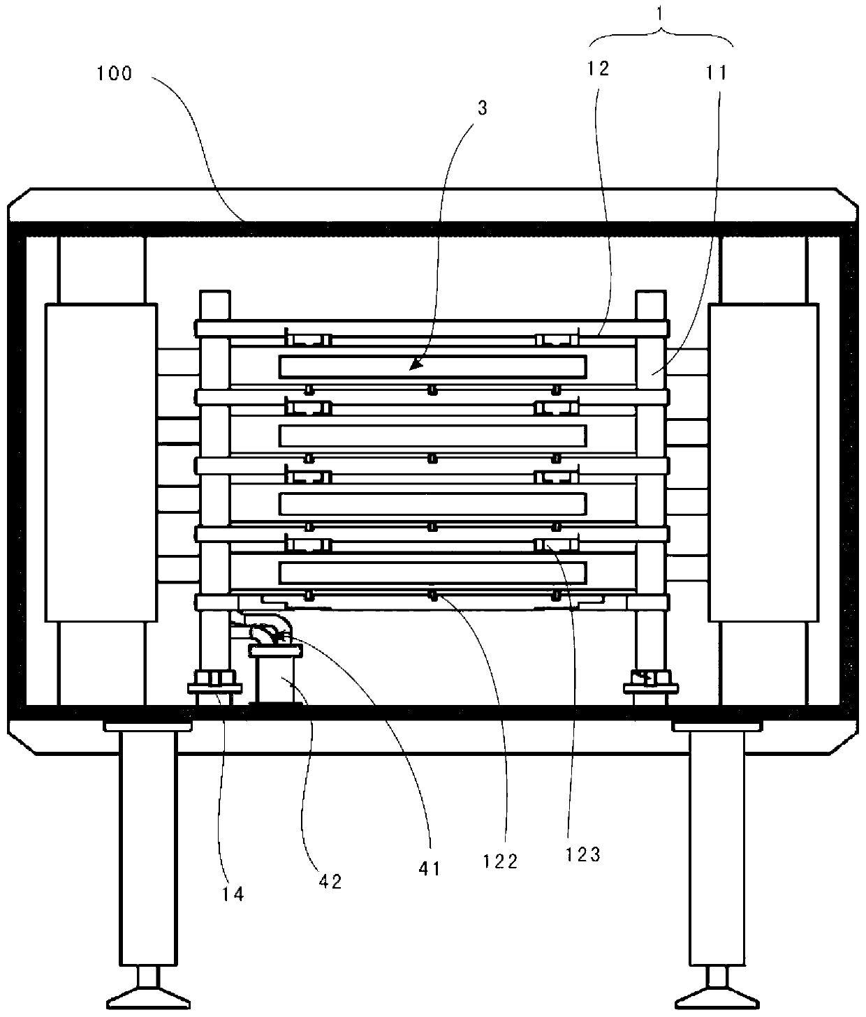
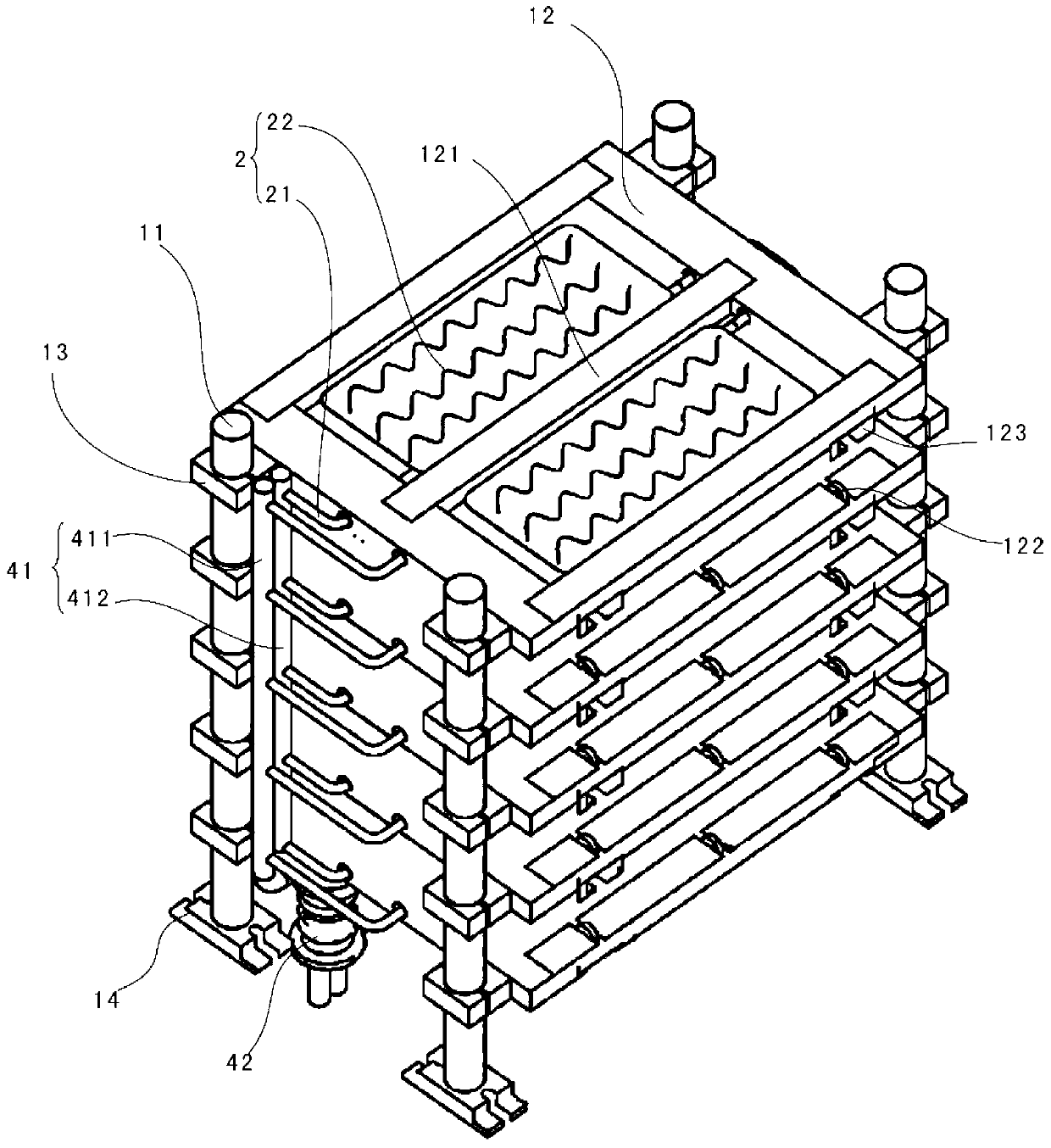
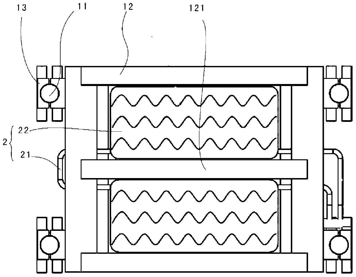
[0024] see figure 1 , a PECVD device provided in a preferred embodiment of the present invention, including a process chamber 100, and a carrier 1 and five cooling vapor chambers 2 (such as figure 2 shown) and four reaction chambers 3.

[0025] In this embodiment, the process chamber 100 is in the shape of a square as a whole, and a stainless steel mirror heat-insulating reflector is installed on its inner surface, which can effectively prevent heat from being emitted to the external environment in the form of radiation, and further save energy.

[0026] Such as figure 1 , figure 2 As shown, the carrier 1 is slidably placed in the process chamber 100 . A pulley 14 is installed on the bottom of the carrier frame 1. In this embodiment, the carrier frame 1 includes four sup...


PUM

PropertyMeasurementUnit
Diameteraaaaaaaaaa

Abstract

The invention discloses a plasma enhanced chemical vapor deposition (PECVD) device which comprises a process cavity, and a bearing rack, cooling vapor chambers and at least one reaction chamber which are arranged in the process cavity, wherein the multiple vapor chambers are arranged on the bearing rack in a layered arrangement mode along the vertical direction; the reaction chamber is horizontally arranged between two adjacent vapor chambers; and the vapor chambers are arranged on the upper and lower sides of each reaction chamber. The vapor chambers are arranged on the upper and lower sides of each reaction chamber; due to the uniform heating and isolating functions of the vapor chambers, the heat radiation interference between the reaction chambers is eliminated, and the temperature consistency in each reaction chamber is guaranteed; and meanwhile, the cooling vapor chamber has the cooling effect, the temperature of the process cavity is prevented from being extremely high, and the sealing structure of the process cavity is protected, so that the temperature of the process cavity is prevented from being extremely low, and the waste of heating energy is avoided.

Description

technical field [0001] The invention relates to the field of vacuum coating, in particular to a PECVD device. Background technique [0002] Plasma Enhanced Chemical Vapor Deposition (PECVD) technology is a technology that uses plasma discharge to generate charged particles, free radicals, active groups and other substances to undergo chemical reactions on the substrate surface to deposit thin films. Because the plasma stimulates the activity of the reactive gas molecules, the temperature of the deposition film process becomes lower, and the deposition rate is fast, the grown film has good compactness, less defects, and good process repeatability, so it is widely used. It was first used in the semiconductor chip processing industry to deposit silicon oxide and silicon nitride films; in recent years, with the vigorous development of liquid crystal flat panel display technology and solar photovoltaic industry, PECVD technology is used to prepare thin-film transistors (Thin-Film...

Claims


Application Information

Patent Timeline
IPC IPC(8): C23C16/513C23C16/455C23C16/52
Inventor 何祝兵王春柱苏奇聪
Owner SOUTH UNIVERSITY OF SCIENCE AND TECHNOLOGY OF CHINA
Learn More