
Ribbed steel tube concrete column and its design method

A technology of concrete column and design method, which is applied to columns, piers, pillars, etc., can solve the problems of increasing welding workload and processing costs, increasing the complexity of steel pipe processing, increasing the wall thickness of steel pipes, and shortening the processing period. , high rigidity, the effect of reducing wall thickness

Active Publication Date: 2016-06-22
CENT RES INST OF BUILDING & CONSTR CO LTD MCC GRP +1
View PDF6 Cites 1 Cited by
  • Summary
  • Abstract
  • Description
  • Claims
  • Application Information

AI Technical Summary

Problems solved by technology

Under the condition of a certain steel pipe diameter, in order to meet the diameter or width-thickness ratio requirements, it is necessary to increase the wall thickness of the steel pipe, resulting in an increase in steel consumption; the installation of longitudinal stiffeners increases the complexity of steel pipe processing, increases the welding workload and Processing costs, extended construction period

Method used


Image

  • Ribbed steel tube concrete column and its design method
  • Ribbed steel tube concrete column and its design method
  • Ribbed steel tube concrete column and its design method

Examples


Embodiment 1

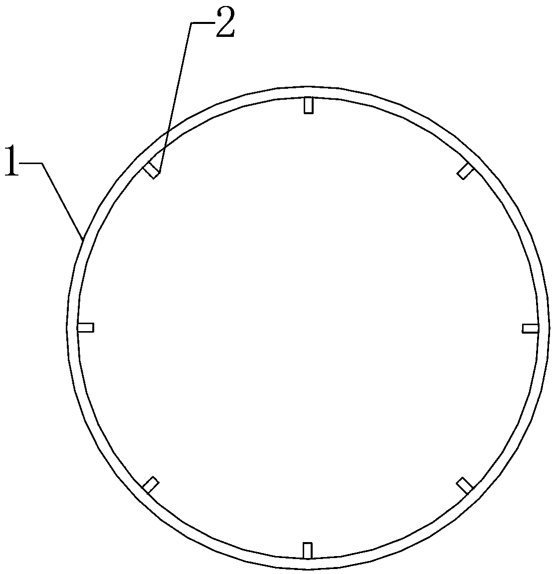
[0046] Such as figure 1 As shown, the ribbed steel pipe is a round steel pipe. During the manufacturing process, the steel plate 1 is continuously rolled on a rolling mill of a steel factory, and a plurality of ribs 2 are rolled on the rolling surface.

[0047] The distribution of ribs on the ribbed steel plate can have the following situations:

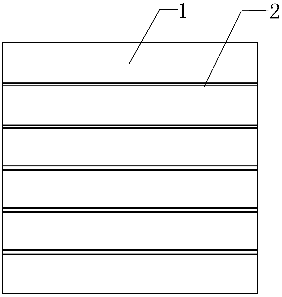
[0048] Such as Figure 3-Figure 5 As shown, the ribs on the ribbed steel plate are distributed on one or both sides of the steel plate.

[0049] Such as image 3 , Figure 6-Figure 7 As shown, the ribs on the ribbed steel plate are continuous or discontinuous; the ribs are horizontally parallel or obliquely parallel.

[0050] The further operation of the rolled ribbed steel plate is: roll the ribbed steel plate into a cylindrical shape, and attach and weld the two welded ends to finally become a ribbed steel pipe.

[0051] The finished ribbed steel pipe will be further explained according to the distribution of the ribs. For s...

Embodiment 2

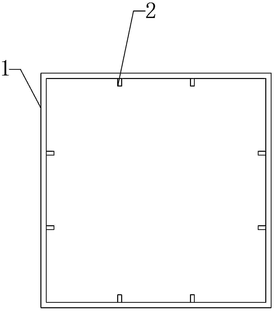
[0054] Such as figure 2 As shown, the ribbed steel pipe is a square steel pipe. During the production process, the steel plate is continuously rolled on the rolling mill of the steel mill, and multiple ribs are rolled on the rolling surface.

[0055] The distribution of ribs on the ribbed steel plate can have the following situations:

[0056] Such as Figure 3-Figure 5 As shown, the ribs on the ribbed steel plate are distributed on one or both sides of the steel plate.

[0057] Such as image 3 , Figure 6-Figure 7 As shown, the ribs on the ribbed steel plate are continuous or discontinuous; the ribs are horizontally parallel or obliquely parallel.

[0058] Since square steel pipes are complicated to be rolled or bent, the further operation of the rolled ribbed steel plate is as follows:

[0059] For welding and forming of four ribbed steel plates:

[0060] The four ribbed steel plates are provided with grooves on their respective welding ends, and the direction of th...


PUM


Abstract

The invention discloses a ribbed steel tube, a concrete-filled ribbed steel tube column and a designing method of the ribbed steel tube. The concrete-filled ribbed steel tube column comprises a ribbed steel tube and a concrete column filled in the ribbed steel tube, wherein the ribbed steel tube is formed by turning, rolling or bending and welding a ribbed steel plate where ribs are rolled. A conventional stiffened concrete-filled steel tube column is replaced with the concrete-filled ribbed steel tube column, and compared with the conventional stiffened concrete-filled steel tube column, the welding work amount and the processing cost are reduced due to the fact that the ribs are rolled; and the processing period can be effectively shortened, and the quality stability is better.

Description

technical field [0001] The invention relates to the field of construction engineering, in particular to a ribbed steel pipe concrete column and a design method thereof. Background technique [0002] In the building structure, due to the advantages of high tensile strength of steel pipe and high compressive strength of concrete, CFST column has many advantages such as high strength, high rigidity, good plasticity and toughness. In order to prevent local buckling of steel pipes in CFST columns, the diameter or width-to-thickness ratio of steel pipes needs to be limited, and longitudinal stiffeners should be provided when necessary. Under the condition of a certain diameter of steel pipe, in order to meet the requirements of diameter or width-thickness ratio, it is necessary to increase the wall thickness of the steel pipe, resulting in an increase in steel consumption; setting longitudinal stiffeners increases the complexity of steel pipe processing, increases the welding work...

Claims


Application Information

Patent Timeline
Patent Type & Authority Patents(China)
IPC IPC(8): E04C3/34
Inventor 岳清瑞龚超侯兆新郑云秦国鹏吴明超周建锋
Owner CENT RES INST OF BUILDING & CONSTR CO LTD MCC GRP
Learn More