Sample room for analyzing liquid absorption spectrum

An absorption spectrum and liquid sample technology, applied in the field of optical devices, can solve the problems of large volume of liquid samples, difficulty in miniaturization of spectroscopic instruments, evaporation and leakage of volatile components, etc., and achieve the effect of high signal-to-noise ratio

Active Publication Date: 2013-09-04
徐姗
View PDF5 Cites 5 Cited by
  • Summary
  • Abstract
  • Description
  • Claims
  • Application Information

AI Technical Summary

Problems solved by technology

Devices for collecting liquid absorption spectrum signals such as cuvettes have the following defects: (1) The cleaning is cumbersome, especially when the liquid sample contains oil or other substances with strong adhesion; (2) The light-transmitting surface is easily worn during the cleaning process , causing measurement errors; (3) to collect the ultraviolet absorption spectrum signal of the sample, it needs to be made of relatively expensive quartz glass; (4) the cuvette, flow cell or porous plate structure has a large volume and is placed inside the equipment. It is difficult to realize the miniaturization of spectroscopic instruments; (5) It is difficult to realize accurate and sensitive temperature control of liquid samples due to the small heat transfer surface per unit volume of the measured sample; (6) It is difficult to seal, and the volatile components of liquid samples are easy to evaporate and leak
Although this structure removes the restriction on the optical properties of the liquid sample holding container and is conducive to the miniaturization of spectroscopic instruments, t

Method used


Image

  • Sample room for analyzing liquid absorption spectrum
  • Sample room for analyzing liquid absorption spectrum

Examples


Embodiment Construction

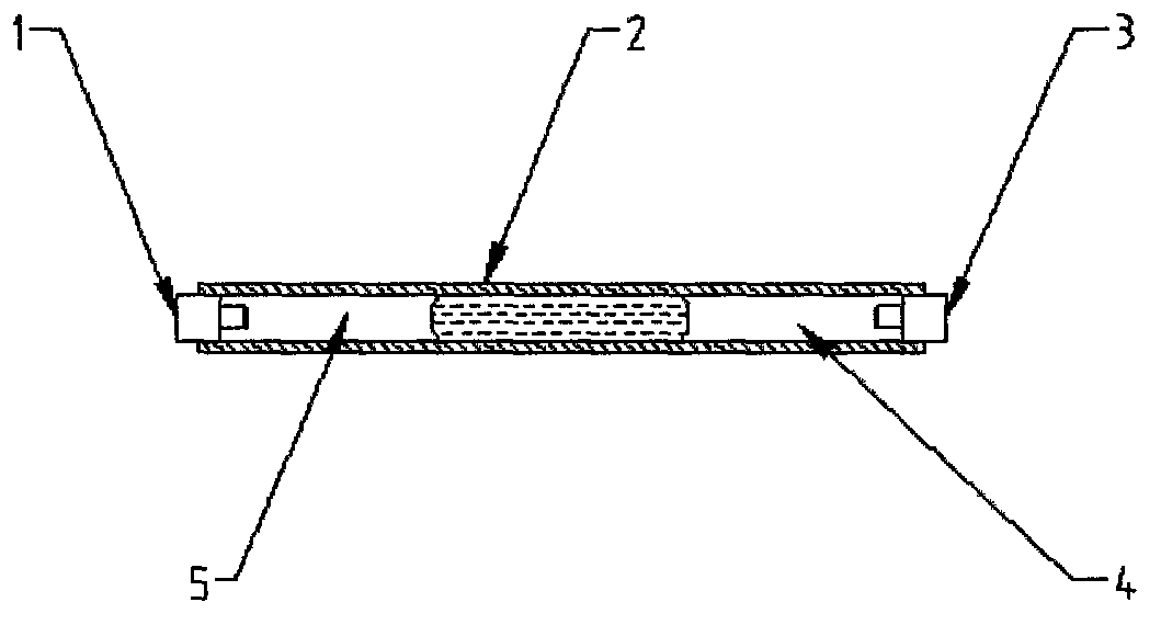
[0019] The liquid absorption spectrum sample chamber includes a sample tube, a light emitting end and a light receiving end. The lumen of the sample tube is used to carry the liquid sample; the light emitting end is located at one end of the sample tube for introducing light beams; the light receiving end is located at the other end of the sample tube for receiving the light beam passing through the liquid sample. A protective gas column exists in the sample lumen between the liquid sample and the transmitting end and between the liquid sample and the receiving end to isolate the liquid sample from the light emitting end and the light receiving end.

[0020] In the liquid absorption spectrum sample chamber, there is only the gas in the protective gas column between the liquid sample and the transmitting end, without any other solid medium; there is only the gas in the protective gas column between the liquid sample and the receiving end, without any other solid medium.

[002...


PUM

PropertyMeasurementUnit
The inside diameter ofaaaaaaaaaa

Abstract

The invention provides an absorption spectrum collection sample room for analyzing a liquid absorption spectrum. The sample room comprises a sample tube, a light beam transmitting end and a light beam receiving end, wherein a cavity of the sample tube is used for carrying a liquid sample; the light beam transmitting end is connected with a port of the sample tube, and a light beam is guided along the longitudinal direction of the sample tube; the light beam receiving end is connected with the other port of the sample tube to receive the light beam which passes through the liquid sample in the cavity of the sample tube; and the inner wall material of the sample tube and the cross sectional dimension of the cavity of the sample tube are selected to realize that the liquid sample can form a liquid column, which is separated from the two ports, in the horizontal sample tube due to solid-liquid interface tension between the liquid sample and the inner wall of the sample tube, so that the light path of the light beam in the sample tube is from the light beam transmitting end, an air column, the liquid column, an air column to the light beam receiving end in sequence when the absorption spectrum is collected. After the structure and the light path are adopted, the liquid sample, the light beam transmitting end and the light beam receiving end are separated from one another by the air columns, so that the condition that an optical interface is polluted can be avoided, the thickness of an absorption layer can be adjusted and controlled by the volume of added liquid according to actual requirements, and an absorption spectrum signal with higher signal to noise ratio can be obtained.

Description

technical field [0001] The invention relates to an optical device applied in the field of analytical chemistry, in particular to a sample chamber used in liquid absorption spectrum analysis to collect the absorption spectrum of a liquid sample, and to a method for using the sample chamber to collect the absorption spectrum. Background technique [0002] The use of spectral signals of substances, especially absorption spectral signals, can realize rapid qualitative and quantitative analysis of chemical composition and chemical structure of substances, and is an important means in the field of analytical chemistry. To collect the absorption spectrum of a sample, it is necessary to build a reasonable sample carrying structure to minimize the interference caused by external environmental factors and manual operations, so as to ensure that the collected signal can objectively reflect the characteristic chemical information of the sample, and can be used as a qualitative Basis for...

Claims


Application Information

Patent Timeline
IPC IPC(8): G01N21/03G01N21/31
Inventor 徐姗
Owner 徐姗
Why Eureka
Try Eureka