Multi-phase motor winding switching circuit
A technology of winding switching and multi-phase motors, which is applied in the direction of AC motor control, electrical components, control systems, etc., can solve the problems of low energy utilization and achieve the effects of small quantity, small influence, and low loss
- Summary
- Abstract
- Description
- Claims
- Application Information
AI Technical Summary
Problems solved by technology
Method used
Image

Examples
specific Embodiment approach 1
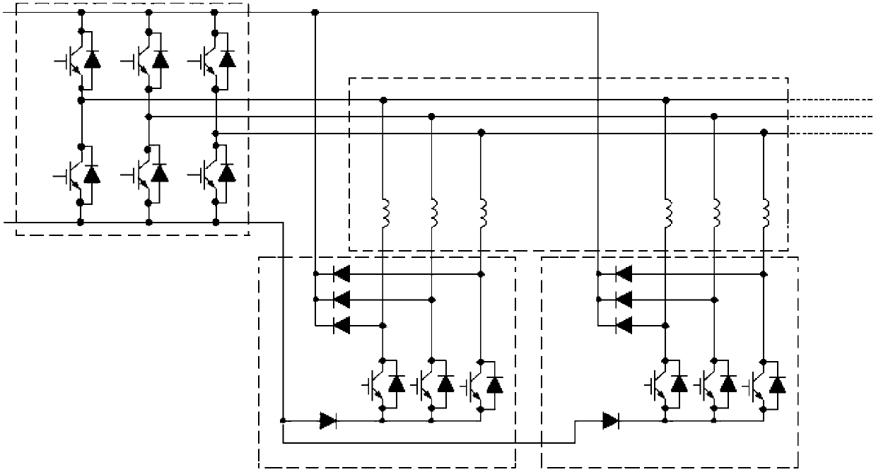
[0034] Specific implementation mode one: see figure 1 Describe this embodiment, the multi-phase motor winding switching circuit described in this embodiment, the multi-phase motor is an m-phase motor, and m≥3, the m-phase motor has n winding units and an inverter, and the inverter It is an m-phase bridge inverter, in which m first ends of each winding unit are connected to m output buses of the inverter, and it includes n winding switching circuit units, and each winding switching circuit unit includes a switching circuit unit and a clamping circuit unit; each switching circuit unit is composed of m switching units, each switching unit is composed of a switching tube, and each clamping circuit unit is composed of m+1 diodes,
[0035] Each tail end of each winding unit is correspondingly connected to the collector of the switching tube of one switching circuit unit of the n winding switching circuit units, and the emitters of the switching tubes of the m switching units of eac...
specific Embodiment approach 2
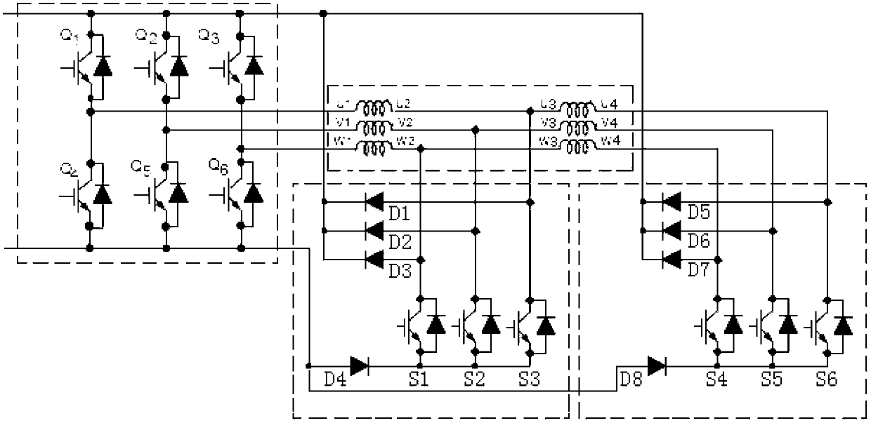
[0038] Specific implementation mode two: see figure 2 Describe this embodiment, the multi-phase motor winding switching circuit described in this embodiment, the multi-phase motor is an m-phase motor, and m≥3, the m-phase motor has n winding units and an inverter, and the inverter It is an m-phase bridge inverter, in which the corresponding phases of each winding unit are connected in series in sequence, and the m first terminals of the series-connected windings are connected to the m output terminals of the inverter, which includes n winding switching circuit units , each winding switching circuit unit includes a switching circuit unit and a clamping circuit unit; each switching circuit unit is composed of m switching units, each switching unit is composed of 1 switching tube, and each clamping circuit unit is composed of m+1 composed of diodes,
[0039] Each tail end of each winding unit is correspondingly connected to the collector of the switching tube of one switching c...
specific Embodiment approach 3
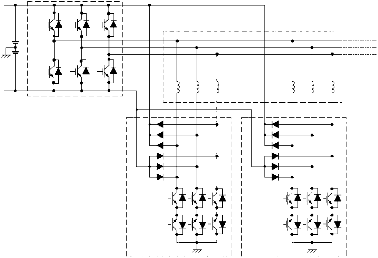
[0042] Specific implementation mode three: see image 3 Describe this embodiment, the multi-phase motor winding switching circuit described in this embodiment, the multi-phase motor is an m-phase motor, and m≥3, the m-phase motor has n winding units and an inverter, and the inverter It is an m-phase half-bridge inverter powered by positive and negative dual power supplies, in which m first ends of each winding unit are connected to m output busbars of the inverter, and it includes n winding switching circuit units, each Each winding switching circuit unit includes a switching circuit unit and a clamping circuit unit; each switching circuit unit is composed of m switching units, each switching unit is composed of 2 switching tubes, and the emitters of the 2 switching tubes are connected together. A clamping circuit unit consists of 2m diodes,
[0043] The m collectors of the m switching units of each switching circuit unit are respectively connected with the m tail ends of eac...
PUM
 Abstract
Description
Claims
Application Information
 - R&D
- Intellectual Property
- Life Sciences
- Materials
- Tech Scout
- Unparalleled Data Quality
- Higher Quality Content
- 60% Fewer Hallucinations
Browse by: Latest US Patents, China's latest patents, Technical Efficacy Thesaurus, Application Domain, Technology Topic, Popular Technical Reports.
© 2025 PatSnap. All rights reserved.Legal|Privacy policy|Modern Slavery Act Transparency Statement|Sitemap|About US| Contact US: help@patsnap.com