Passive optical network equipment

A passive optical network and equipment technology, which is applied in the direction of electromagnetic network arrangement, multiplexing system selection device, electrical components, etc., can solve the problems that cannot be popularized, cannot be adjusted, and is not easy to weld, etc., to reduce costs , Overcoming high cost, improving production efficiency and yield

Inactive Publication Date: 2013-09-04
苏州优康网络电子商务有限公司
View PDF4 Cites 1 Cited by
  • Summary
  • Abstract
  • Description
  • Claims
  • Application Information

AI Technical Summary

Problems solved by technology

[0003] However, the existing network equipment that realizes the optical transceiver module often has difficu

Method used


Image

  • Passive optical network equipment

Examples


Embodiment Construction

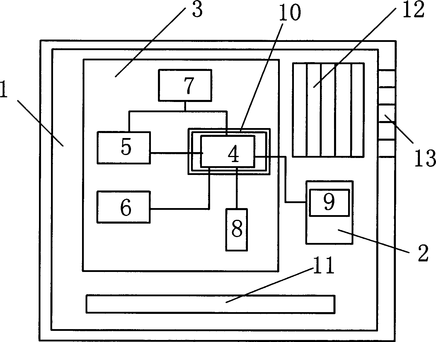
[0026] Such as figure 1 The passive optical network equipment shown includes an equipment box body 1, and a box cover is arranged on the equipment box body 1. The special feature is that the equipment box body 1 used in the present invention is distributed with an optical transceiver module interface device 2, The PON main chip 4 , the clock control device 5 , the storage device 6 , the energy supply device 7 , the network port communication device 8 and the laser drive limiting amplifier 9 are arranged on the main circuit board 3 . Specifically, the storage device 6 and the network port communication device 8 are respectively connected to the PON main chip 4 through an interface bus, and the clock control device 5 is connected to the PON main chip 4 . At the same time, the PON main chip 4 is connected to the laser driving limiting amplifier 9 through the interface bus, and the interface device 2 of the optical transceiver module is connected to the main circuit board 3 . Cer...


PUM


Abstract

The invention relates to passive optical network equipment which comprises an equipment box body. A box cover is arranged on the equipment box body. The passive optical network equipment is characterized in that an optical transceiver module connector device, a PON main chip arranged on a main circuit board, a clock control device, a storing device, an energy supply device, an internet access communication device and a laser driving limiting amplifier are distributed in the equipment box body. The storing device and the internet access communication device are respectively connected with the PON main chip through connector buses. The clock control device is connected with the PON main chip which is connected with the laser driving limiting amplifier through a connector bus. The optical transceiver module connector device is connected with the main circuit board. Accordingly, based on matching of the PON main chip and the clock control device, communication transmission effect is improved. The problems that in the prior art, cost is high, production is not easy, and reject ration is high are overcome, equipment cost can be effectively lowered, and production efficiency and finished product rate are improved.

Description

technical field [0001] The invention relates to a network device, in particular to a passive optical network device. Background technique [0002] As a next-generation broadband access technology, passive optical network (PON) technology has the advantages of high bandwidth, low maintenance cost, high reliability, strong service carrying capacity, long transmission distance, etc., and can save fiber resources. main solution. However, higher cost restricts the development of PON technology. The cost of PON equipment is mainly composed of three aspects: PON solution chip, peripheral peripheral devices, and optical transceiver module. [0003] However, the existing network equipment that realizes the optical transceiver module often has difficulties in soldering, soldering, adjustment, and high defect rate during production, so it cannot be widely used. Contents of the invention [0004] The object of the present invention is to provide a passive optical network device in ...

Claims


Application Information

Patent Timeline
IPC IPC(8): H04Q11/00H04B10/27
Inventor 周国峰
Owner 苏州优康网络电子商务有限公司
Why Eureka
Try Eureka