Laminate structure

一种子层、带片的技术,应用在风扇容纳壳体领域,能够解决桨叶撞击机身燃料箱、损坏等问题

Active Publication Date: 2013-09-04
GKN AEROSPACE SERVICES LTD
View PDF4 Cites 1 Cited by
  • Summary
  • Abstract
  • Description
  • Claims
  • Application Information

AI Technical Summary

Problems solved by technology

Without a fan case, all or part of the blade could strike the airframe and / or fuel tank, causing catastrophic damage

Method used


Image

  • Laminate structure
  • Laminate structure
  • Laminate structure

Examples


Embodiment Construction

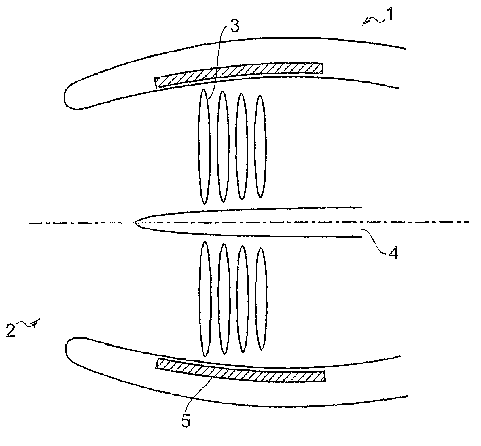
[0080] Figure 1 shows a cross-sectional view of a gas turbine engine. Rather, the cross-sectional view shows the location of a fan housing housing according to one application and embodiment of the invention.

[0081] As shown in Figure 1, a gas turbine engine 1 includes an inlet 2 for admitting air into the engine. This simplified figure shows fan blades 3 on a central rotatable shaft 4 . It is desirable in engine manufacture to have some form of protective barrier put in place around the turbine blades so that complete or partial failure of one blade does not cause that portion to radially disengage from the engine. It will be appreciated that a failed portion of the blade coming out of the engine could result in a catastrophic event.

[0082] To prevent this from occurring and to keep the blades inside the engine, a fan casing 5 is located around the blades. It has been recognized that manufacturing the part from composite materials would significantly reduce the weight ...


PUM


Abstract

A method of forming a composite component in which the component comprises a series of sub -layers and in which the sub -layers are offset with respect to one or all of the other sub -layers forming the composite component.

Description

technical field [0001] The present invention relates to a method for forming a one-piece composite part with improved structural and crash performance. In particular, but not exclusively, the present invention relates to improved fan containment casings for gas turbine engines and the like. Background technique [0002] Composite materials have been used in the aerospace industry for many years. The term composite (also often referred to as 'composite') is used to describe materials that include fibers such as carbon, glass, and epoxy (or similar). Composite materials offer significant advantages such as light weight, improved fatigue / damage resistance, corrosion resistance, and negligible thermal expansion for aerospace applications. [0003] These materials have dramatically increased use throughout the aerospace industry due to fuel savings, which can be achieved over the life of the aircraft by reducing the overall gross weight of the various components that make up th...

Claims


Application Information

Patent Timeline
Patent Type & Authority Applications(China)
IPC IPC(8): B29C70/30B29C70/08
CPCB29C70/083B29C70/30Y10T428/24752Y10T156/10B29C70/38B29C70/021F01D25/24
Inventor M·高恩P·安德森G·马伦戈
Owner GKN AEROSPACE SERVICES LTD
Why Eureka
Try Eureka