Ultrasonic resonance spectrum detection method for fatigue hardening layer of roll

A fatigue-hardened layer and detection method technology, applied in the direction of length measuring device, metal rolling, metal rolling, etc., can solve the problems of unsuitability for fatigue-hardened layer, large data dispersion, large workload, etc.

Active Publication Date: 2013-09-11
BAOSHAN IRON & STEEL CO LTD
View PDF4 Cites 6 Cited by
  • Summary
  • Abstract
  • Description
  • Claims
  • Application Information

AI Technical Summary

Problems solved by technology

Hardness testing is a kind of dynamic force testing. The commonly used Shore hardness tester is a portable portable instrument, which is convenient for on-site testing. It has a simple structure, is easy to operate, and has high testing efficiency. Compared with the traditional method, the accuracy is slightly worse. Due to the influence of factors such as the verticality of the test and the surface finish of the sample, the data dispersion is relatively large. The comparison of the test results is limited to materials with the same elastic modulus. The thickness of the sample and the The weight has certain requirements, and it is not suitable for a thinner fatigue-hardened layer, and there are differences in the hardness of the roll body, so it is difficult to accurately quantify and evaluate the microscopic fatigue-hardened layer.
[0008] 3) X-ray detecti...

Method used


Image

  • Ultrasonic resonance spectrum detection method for fatigue hardening layer of roll
  • Ultrasonic resonance spectrum detection method for fatigue hardening layer of roll
  • Ultrasonic resonance spectrum detection method for fatigue hardening layer of roll

Examples


Embodiment Construction

[0045] The specific implementation of the present invention will be described in detail below in conjunction with the drawings of the embodiments.

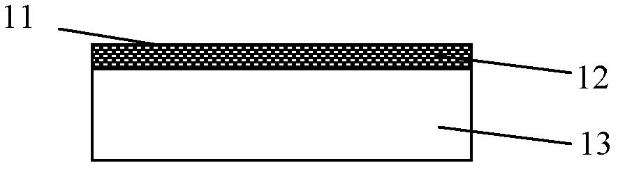
[0046] For different used rolls, such as cold-rolled work rolls, cold-rolled backup rolls, hot-rolled backup rolls, etc., such as figure 1 As shown, below the roll surface 11 is the fatigue hardened layer 12 first, and then the roll working layer 13.

[0047] After the fatigue hardened layer is formed by the used rolls, the structure of the fatigue hardened layer will be different from that of the working layer matrix. The analysis shows that the lath martensite boundary of the material matrix with a depth of less than 1mm on the surface is clearly distinguishable, and it is not affected. Contact fatigue is affected, while the boundary of the sample at 10 microns is blurred, and the structure looks like secondary grains, which is affected by contact fatigue.

[0048] The present invention is to perform ultrasonic resonance spectrum detec...


PUM


Abstract

The invention provides an ultrasonic resonance spectrum detection method for a fatigue hardening layer of a roll, relates to the roll surface NDT (non-destructive testing) technology, and solves the problems that the conventional fatigue hardening layer of the roll cannot be detected quantitatively and the thickness requirement for the fatigue hardening layer to be tested is high. The ultrasonic resonance spectrum detection method comprises the steps that the roll surface is processed with uniform roughness; wideband ultrasonic signals are emitted to the fatigue hardening layer of the roll to cause resonance of the fatigue hardening layer, and the ultrasonic resonance circular frequency and the resonance amplitude are obtained; ultrasonic resonance spectrum signals in a certain band of the ultrasonic resonance frequency centroid; a signal spectral peak is detected from an ultrasonic resonance frequency position in the band, and is compared with a spectral peak of a standard test block provided with the fatigue hardening layer under the same detection conditions; the intensity of the spectral peak obtained through detection is subjected to quantization processing with an amplitude quantitative method; and a formant detection quantization distribution diagram for various positions of the whole roll body is formed through image visualization processing. The ultrasonic resonance spectrum detection method can be used for effective quantitative detection for various thicknesses of the fatigue hardening layer of the roll.

Description

Technical field [0001] The invention relates to a non-destructive detection technology for the surface of a roll, in particular to an ultrasonic resonance spectrum detection method for a fatigue hardened layer of a roll. Background technique [0002] The rolling mill is the key process equipment of modern metallurgical enterprises, and the roll is the key core component of the rolling mill. Its performance directly determines the stability of the rolling mill, the smooth production line, production consumption and product quality. [0003] The most economical and safe use of the roll is of great significance to production. If the contact fatigue stress of the roll is large when the roll is working, it will cause a fatigue hardening layer on the surface of the roll. The contact fatigue damage caused by it is a common phenomenon in many steel enterprises. In order to prevent roll cracking and peeling accidents, it is necessary to develop a non-destructive testing technology for roll ...

Claims


Application Information

Patent Timeline
IPC IPC(8): B21B38/00
Inventor 张国星孙大乐
Owner BAOSHAN IRON & STEEL CO LTD
Why Eureka
Try Eureka