Magnesium alloy stamping process

A magnesium alloy and process technology, applied in the field of magnesium alloy stamping process, can solve the problems of increased thickness distribution difference of stamping parts, affect the dimensional stability of stamping parts, limit the stamping performance of stamping parts, etc., achieve uniform thickness distribution and improve stamping performance , to ensure the effect of stability

Active Publication Date: 2014-12-24
CHONGQING UNIV
View PDF7 Cites 0 Cited by
  • Summary
  • Abstract
  • Description
  • Claims
  • Application Information

AI Technical Summary

Problems solved by technology

[0002] In the field of mechanical processing and stamping technology, isothermal stamping and differential temperature stamping are usually used for the stamping of light alloys such as magnesium alloys. Among them, isothermal stamping can significantly improve the plastic deformation of magnesium alloys and other light alloys. Formability, but it is easy to produce concentrated plastic deformation at the rounded corner of the punch during the forming process, resulting in premature cracking of stamping parts, thus limiting the stamping performance of light alloy stamping parts such as magnesium alloys
[0003] The other uses differential temperature stamping to form a certain temperature gradient in the sheet, which can effectively improve the stamping performance of light alloys such as magnesium alloys. However, as the temperature decreases, the springback of light alloys will increase sharply. It will seriously affect the dimensional stability of stamping parts and increase the difference in thickness distribution of stamping parts

Method used


Image

  • Magnesium alloy stamping process

Examples


Embodiment Construction

[0021] The preferred embodiments of the present invention will be described in detail below with reference to the accompanying drawings.

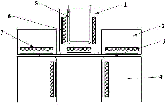
[0022] Such as figure 1 Shown is the structural schematic diagram of the mold that implements magnesium alloy stamping process of the present invention, and this mold comprises punch 1, die 4 and crimping die 2, and the resistance wire 7 that is used for heating is all arranged in die 4 and crimping die 2 1. A thermocouple 6 for precise control of the heating temperature, a resistance wire 7 for heating, a thermocouple 6 for precise control of the heating temperature and a circulating cooling channel 5 for controlling the temperature of the punch at a low temperature are arranged in the punch 1, Magnesium alloy stamping process of the present invention, its stamping steps are as follows:

[0023] 1) Before stamping, the magnesium alloy sheet 3 coated with high temperature resistant oil is placed between the die 4 and the blank holder 2, th...


PUM


Abstract

The invention discloses a magnesium alloy stamping process aiming at improving stamping performance of magnesium alloy by stepwise controlling temperature of a convex die. The punching process includes the following steps: 1), before stamping, disposing a magnesium alloy plate coated with high-temperature-resistant oil between a concave die and a blank pressing die, enabling the convex die to contact with the surface of the plate, heating the concave die and the bland pressing die to enable temperature of the both to be controlled between 200 DEG C and 250 DEG C, heating the convex die to enable the temperature of the same to be controlled between 30 DEG C and 90 DEG C, performing heat-insulating control on the concave die, the blank pressing die and the convex die until a stable temperature gradient is set up on the plate; stamping for first time, namely, moving the convex die to stamp the plate, enabling the moving distance of the convex die to be larger than or equal to the radius of a round angle of the convex die, fixing the convex die to stop stamping, heating the convex die to enable the temperature of the convex die to be between 200 DEG C and 250 DEG C, performing heat-insulating control on the concave die, the blank pressing die and the convex die until the stable temperature gradient on the plate is eliminated; stamping and forming, namely, continuing to move the convex die to further stamp the plate until the plate is formed.

Description

technical field [0001] The invention belongs to the field of mechanical processing, and in particular relates to a magnesium alloy stamping process. Background technique [0002] In the field of mechanical processing and stamping technology, isothermal stamping and differential temperature stamping are usually used for the stamping of light alloys such as magnesium alloys. Among them, isothermal stamping can significantly improve the plastic deformation of magnesium alloys and other light alloys. However, during the forming process, it is easy to produce concentrated plastic deformation at the rounded corners of the punch, resulting in premature cracking of stamping parts, which limits the stamping performance of lightweight alloy stamping parts such as magnesium alloys. [0003] The other uses differential temperature stamping to form a certain temperature gradient in the sheet, which can effectively improve the stamping performance of light alloys such as magnesium alloys....

Claims


Application Information

Patent Timeline
Patent Type & Authority Patents(China)
IPC IPC(8): B21D22/00B21D37/16
Inventor 张丁非潘复生董井忍柴森森胡光山谌夏
Owner CHONGQING UNIV
Why Eureka
Try Eureka