Vibrating creep forming method and device for metal member

A metal component and creep technology, which is applied in the field of metal component vibration creep forming, can solve the problems of low forming efficiency, poor forming precision, and high component springback rate, and achieve improved forming efficiency, good dimensional stability, and component springback The effect of rate reduction

Active Publication Date: 2012-04-18
CENT SOUTH UNIV
View PDF5 Cites 16 Cited by
  • Summary
  • Abstract
  • Description
  • Claims
  • Application Information

AI Technical Summary

Problems solved by technology

[0003] In order to solve the technical problems of poor forming precision, many times of trial-manufacturing molds, low forming efficiency and high cost caused by excessively high component springback when making curved surface components by creep forming, the present invention provides a creep forming method. Forming method and device capable of effectively reducing spring-back rate of formed component during forming process

Method used


Image

  • Vibrating creep forming method and device for metal member
  • Vibrating creep forming method and device for metal member
  • Vibrating creep forming method and device for metal member

Examples


Embodiment 1

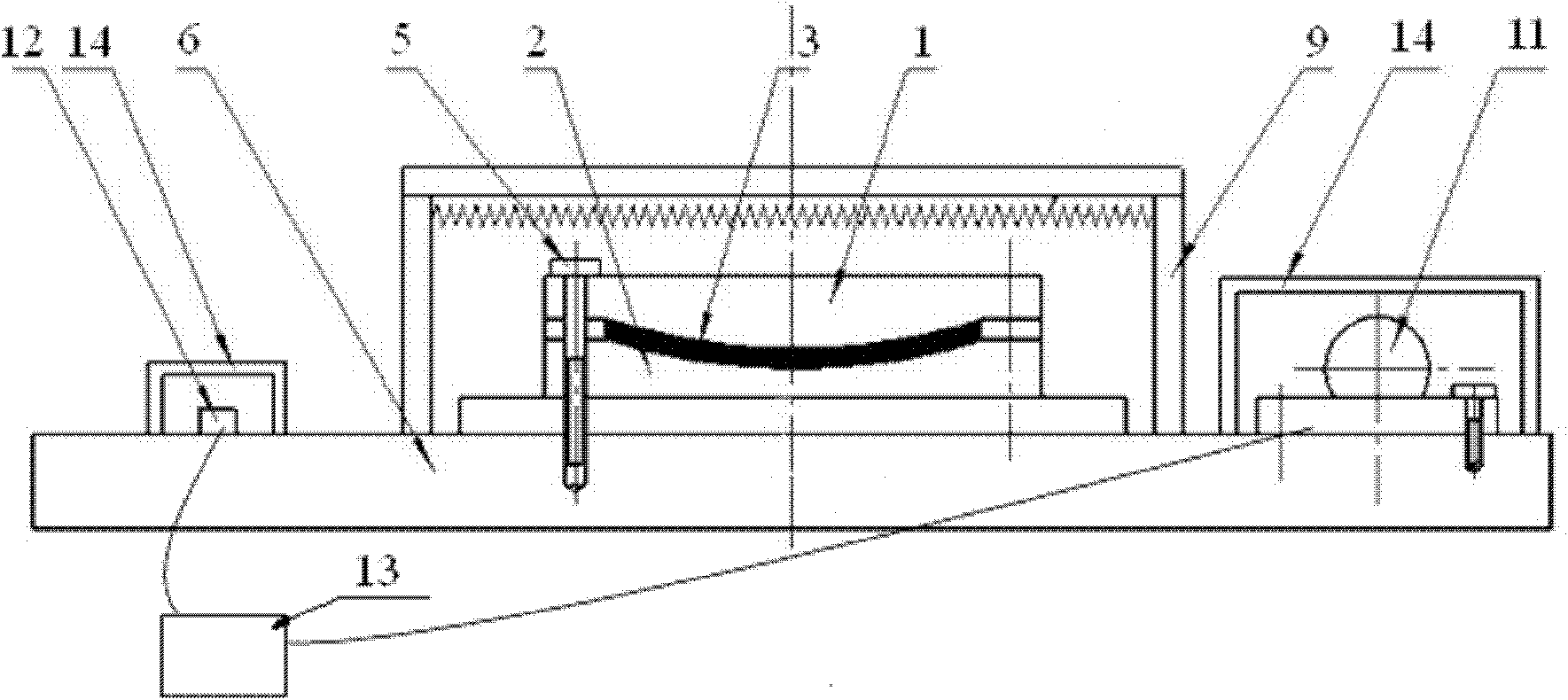
[0022] see figure 1 According to the geometric size and curvature characteristics of the required components, the upper mold 1 and the lower mold 2 are prepared, and the pre-prepared component 3 to be formed is placed in the mold cavity formed by the upper mold 1 and the lower mold 2. Make the upper mold 1, the lower mold 2 closely contact with the component to be formed 3 and keep the pressure, open the locking mechanism 5, fix the upper mold 1, the lower mold 2 and the component to be formed 3 on the vibration platform 6, pass the heating device 9 for heating. The 2024 aluminum alloy billet to be formed has a width of 130mm, a length of 230mm, and a thickness of 5mm. The radius of curvature of the upper and lower molds along the length direction of the plate is R = 1000mm. An exciter is installed on the vibration platform. The heating system during the forming process is 185°C / 6h. During the heating process, the loading time of each vibration is 10 minutes, the intermittent...

Embodiment 2

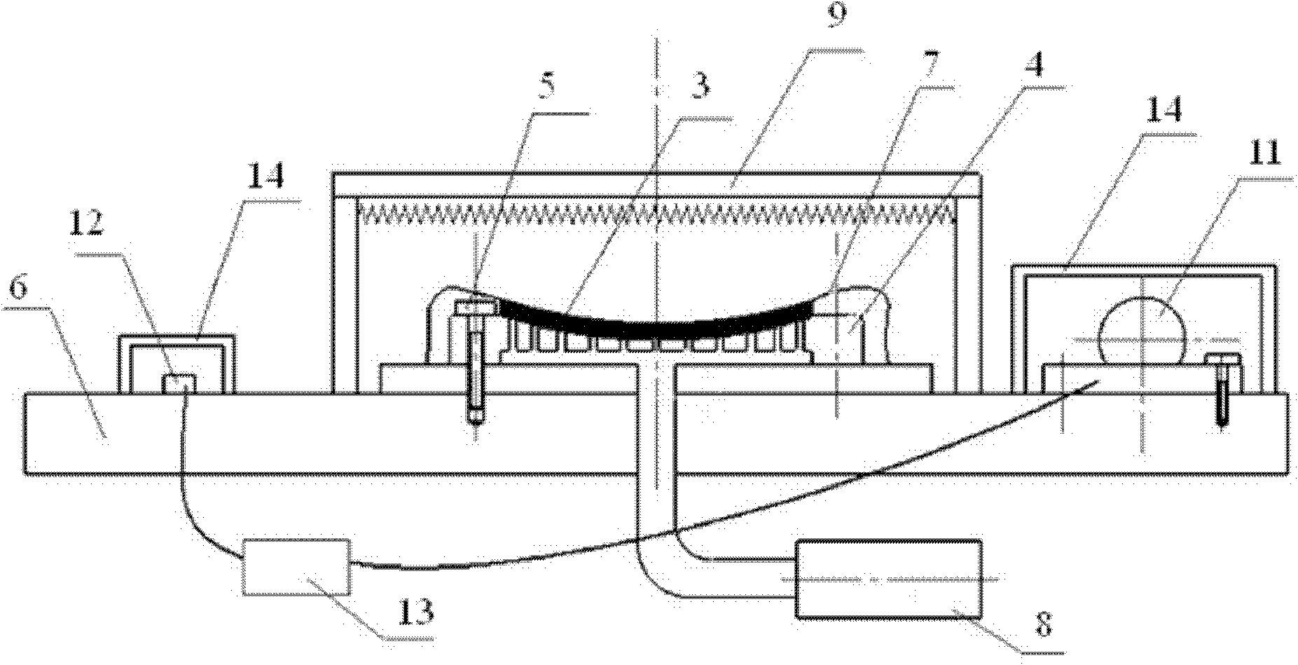
[0024] see figure 2 Prepare the mold 4 according to the geometric dimensions and curvature characteristics of the required components, the mold 4 and the vibration platform 6 are fixed by the locking mechanism 5, put the pre-prepared component 3 to be formed on the mold 4, and seal it with a plastic bag 7 The mold 4 and the blank 3 are pumped to the plastic bag 7 with a vacuum pump 8 until the pressure in the bag drops below 3000 Pa, and the component 3 to be formed is molded under the action of atmospheric pressure, and heated by the heating device 9 . The 7075 aluminum alloy billet to be formed has a width of 65mm, a length of 130mm, and a thickness of 0.5mm. The radius of curvature of the mold along the direction of the plate width is R=1000mm, and the radius of curvature of the mold along the direction of the plate is R=2000mm. Two exciters are installed on the vibration platform. The pressure is 1500Pa, and the heating regime during the forming process is 80°C / 100h. Dur...

Embodiment 3

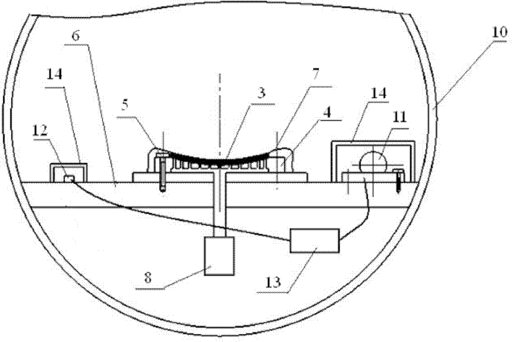
[0026] see image 3Prepare the mold 4 according to the geometric dimensions and curvature characteristics of the required components, the mold 4 and the vibration platform 6 are fixed by the locking mechanism 5, put the pre-prepared component 3 to be formed on the mold 4, and seal it with a plastic bag 7 Mold 4 and blank 3, before or after the sealed plastic bag 7, mold 4, blank 3 and vibration platform are sent into the autoclave 10, the plastic bag 7 is evacuated with a vacuum pump 8 until the pressure in the bag drops below 3000Pa, etc. After the autoclave 10 is sealed, the component to be formed 3 is molded under the action of the air pressure inside the tank, and heated by the autoclave 10 . The 2024 aluminum alloy billet to be formed has a width of 1600mm, a length of 3800mm, and a thickness of 100mm. The radius of curvature of the mold along the length direction of the plate is R=5000mm, the pressure inside the autoclave is 5MPa, and the pressure inside the bag is 2500P...


PUM


Abstract

The invention discloses a vibrating creep forming method for a metal member. A vibrating platform is vibrated by a vibration exciter in the heating process of the member; the device comprises a creep mold, a locking mechanism, the vibrating platform, at least one vibration exciter, an acceleration probe and a frequency-acceleration synchronous tester; the creep mold is fixed on the vibrating platform through the locking mechanism; the vibration exciter and the acceleration probe are fixed on the vibrating platform; and the vibration exciter and the acceleration probe are respectively electrically connected to the frequency-acceleration synchronous tester. According to the method and the device, the member is formed by adopting creep and using micro plastic deformation generated by vibration, so the rebound of the creep formed member can be greatly reduced.

Description

technical field [0001] The invention relates to a method and device for vibration creep forming of metal components, in particular to a method and device for reducing vibration creep deformation of metal components processed by metal blanks using creep and other minor irreversible deformations. Background technique [0002] Creep forming of metal components is a method of material processing using the creep (or stress relaxation) deformation characteristics of metals. The initial part of the elastic deformation of the creep-formed member will be transformed into irrecoverable deformation due to creep, and the remaining elastic part will cause the member to rebound after unloading. Creep forming can be divided into two types according to the way of loading and attaching molds. One is to use the joint action of mold and air pressure to load and attach molds (hereinafter referred to as air pressure loading), and the other is to load and attach molds in contact with molds and me...

Claims


Application Information

Patent Timeline
Patent Type & Authority Applications(China)
IPC IPC(8): B21D31/00
Inventor 邓运来康建可陈泽宇李美春赵建华贺有为唐露华吴阳周筱静张劲李思宇杨金龙张新明
Owner CENT SOUTH UNIV
Why Eureka
Try Eureka