Pectinate gas mixing unit and pectinate gas mixer

A gas mixing and comb-like technology, which is applied in the directions of gas and gas/vapor mixing, fluid mixer, mixer, etc., can solve the problems of high manufacturing cost, long mixed gas path, poor chemical stability, etc. Facilitate large-scale management and reduce the effect of chemical reactions

Active Publication Date: 2013-09-11
王奉瑾
View PDF4 Cites 0 Cited by
  • Summary
  • Abstract
  • Description
  • Claims
  • Application Information

AI Technical Summary

Problems solved by technology

Since a variety of working gases are usually used in the chemical vapor deposition process, and the above two design methods have too long a mixed gas path, because the gas is usually in a high temperature state after entering the gas mixer, and the chemical properties are not stable, so Different types of working gases are prone to chemical reactions on the mixed gas path, and ideally all working gases should react chemically on the substrate surface to form a thin film
For this reason, in order to minimize the degree of reaction of the mixed gas on the mixed gas path, the two setting methods of the central gas flow type and the air cushion floating type need to add a variety of control methods, resulting in the implementation of chemical vapor deposition technology. higher requirements

Method used


Image

  • Pectinate gas mixing unit and pectinate gas mixer
  • Pectinate gas mixing unit and pectinate gas mixer
  • Pectinate gas mixing unit and pectinate gas mixer

Examples


Embodiment 1

[0018] This embodiment is a preferred embodiment of the comb gas mixing unit provided by the present invention, please refer to Figure 1-3 .

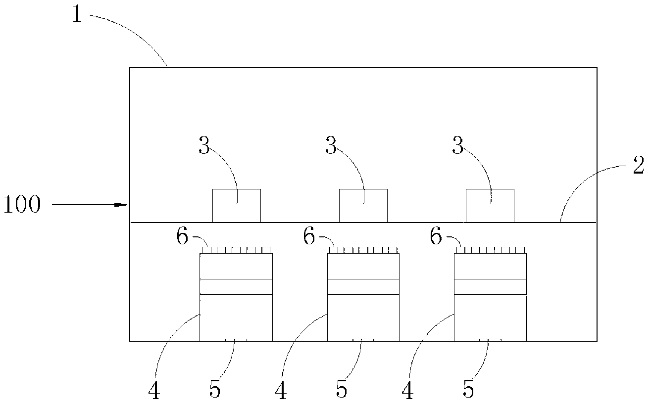
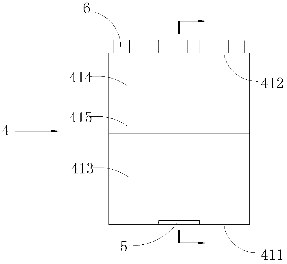
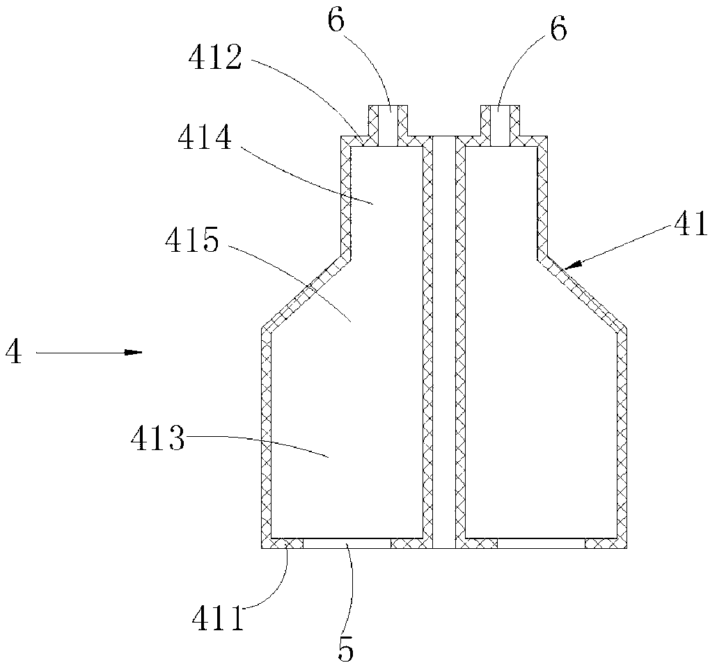
[0019] The comb-shaped gas mixing unit 100 includes a sealed box 1, and a carrier plate 2 is arranged inside the sealed box 1; a plurality of coating areas 3 are arranged on one side of the carrier plate 2, and the other side corresponds to each of the coating areas 3. There are several air injection assemblies 4; the air injection assembly 4 includes at least two air intake chambers 41, any of the air intake chambers 41 is provided with an air inlet 5 on the first box wall 411 away from the carrier plate 1 1. A number of air injection ports 6 are opened on the second box wall 412 close to the loading plate 3 , and the air injection openings 6 are arranged at a distance from the loading plate 2 .

[0020] The comb-shaped gas mixing unit provided by the present invention is provided with a plurality of coating areas 3, and each coating...

Embodiment 2

[0023] This embodiment is a preferred embodiment of the comb-shaped gas mixer provided by the present invention. The comb-shaped gas mixing unit 100 used in this embodiment is based on the comb-shaped gas mixing unit 100 described in Embodiment 1. Please refer to Figure 4 . details as follows:

[0024] The comb-shaped gas mixer includes the comb-shaped gas mixing unit 100 as described in the embodiment and the intake main pipe 7 equal to the number of the air inlets 5 on the same comb-shaped gas mixing unit 100, each of which The air inlets 5 at the same position on the comb gas mixing unit 100 are connected to the same air inlet main pipe 7 through an air inlet branch pipe 8 . The comb-shaped gas mixer provided by the present invention is convenient to realize large-scale management by arranging the comb-shaped gas mixing units provided by the present invention in parallel.


PUM


Abstract

The invention provides a pectinate gas mixing unit. A plurality of film coating regions are arranged, and a gas spraying component corresponds to each film coating region; each gas spraying component comprises at least two gas feeding cavities, so that two or more types of working gas which can not generate chemical reaction can be conveyed by adopting a same gas feeding cavity, and the working gas can be preliminarily mixed in the gas feeding cavity; the working gas from different gas feeding cavities is sprayed out by respective gas spraying openings; the working gas is secondarily mixed in a distance region between each gas spraying opening and a carrying plate. Different types of working gas do not generate chemical reaction during the preliminary mixing and only generate the chemical reaction in the secondary mixing, so that the pectinate gas mixing unit disclosed by the invention can reduce the chemical reaction of the working gas on a mixing gas path. Moreover, the invention also provides a pectinate gas mixer. The pectinate gas mixing units disclosed by the invention are arranged in parallel, so that the large-scale management is facilitated.

Description

technical field [0001] The invention belongs to the field of chemical vapor deposition, in particular to a comb-shaped gas mixing unit and a comb-shaped gas mixer used in chemical vapor deposition equipment. Background technique [0002] Chemical vapor deposition is a chemical technique used to produce solid materials of high purity and high performance. The semiconductor industry uses this technique to grow thin films. A typical CVD process is to expose the wafer (substrate) to one or more different precursors, and a chemical reaction or / and chemical decomposition occurs on the surface of the substrate to produce the film to be deposited. Different by-products are usually produced during the reaction process, but most of them will be taken away with the air flow instead of staying in the reaction chamber. [0003] Chemical vapor deposition technology has been widely used in the field of film coating. In the prior art, the gas mixer in the field of chemical vapor depositio...

Claims


Application Information

Patent Timeline
IPC IPC(8): C23C16/455B01F3/02B01F5/00B01F23/10
Inventor 王奉瑾
Owner 王奉瑾
Why Eureka
Try Eureka