
Bionic optical compound eye of integrated structure

A bionic optics and compound eye technology, applied in the field of bionic optics compound eyes, can solve the problems of heavy workload and high requirements on alignment accuracy, and achieve the effects of improving production efficiency, facilitating high-precision coupling, and improving signal quality

Inactive Publication Date: 2013-09-11
NANCHANG HANGKONG UNIVERSITY
View PDF5 Cites 8 Cited by
  • Summary
  • Abstract
  • Description
  • Claims
  • Application Information

AI Technical Summary

Problems solved by technology

These bionic compound eye optical systems are obtained by high-precision alignment coupling of discrete components, so the workload is heavy and the alignment accuracy is high.

Method used


Image

  • Bionic optical compound eye of integrated structure
  • Bionic optical compound eye of integrated structure
  • Bionic optical compound eye of integrated structure

Examples


Embodiment 1

[0029] Suppose the length of the cylindrical waveguide d=kd 0 +Δd, where k is a non-negative integer, Δd0 . d 0 =4r' / (π / 2-β), which is the distance that the light travels along the optical axis during a period of propagation in the cylindrical waveguide. as attached Figure 5 As shown, the propagation of light from point A to point D is a cycle, and the light transformation matrix of this cycle can prove that when hour,

[0030] M 56 = M BC M B M AB M d 0 k = 1 d 0 2 n - Δd...

Embodiment 2

[0037] when 3 4 d 0 Δd d 0 hour,

[0038] M 56 = M CD M C M BC M B M AB M d 0 k = 1 Δd - d 0 n 0 1 - - - ...


PUM


Abstract

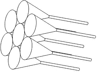
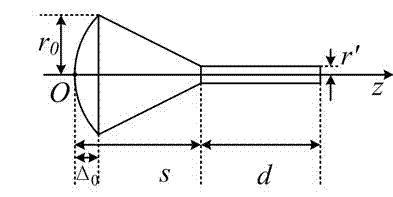
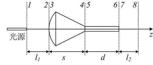
A bionic optical compound eye of an integrated structure belongs to a microstructural optical component and an application field of the microstructural optical component. The bionic optical compound eye is arranged in an ommatidium array according to certain geometric rules of hexagons, squares and the like. Ommatidiums include a micro lens, a crystal cone and a cylindrical waveguide which are coaxial and arranged along the optical axis or the Z axis from the left to the right. No physical distance is arranged between the plano-convex lens and the crystal cone and between the crystal cone and the cylindrical waveguide along the Z axis so as to form a whole. The micro lens can be seen as a plano-convex thin lens. The length from the top end of the micro lens to the tail end of the crystal cone is the focal length of a spherical refraction surface having the same curvature radius and refraction rate as the micro lens sphere. An image space principal point and a focal point of the ommatidiums of the integrated bionic optical compound eye are closely relevant to the length of the cylindrical waveguide. By applying the bionic optical compound eye of the integrated structure to a photoelectric detection system, a photoelectronic imaging system and the like, the system size can be reduced, the system weight is reduced, and complexity of coupling of the bionic optical compound eye with an image sensor or a photoelectric detector can be reduced.

Description

technical field [0001] The invention relates to a bionic optical compound eye with an integrated structure. Background technique [0002] The compound eye of insects in nature is a naturally occurring multi-aperture optical detection system, as well as a naturally occurring real-time image analysis and processing system. It has the characteristics of large field of view, light weight, small size, and sensitivity to moving objects. It is made by researchers. Excellent models of micro-photoelectric sensors, micro-photodetectors, and micro-photoelectric imaging systems. The research results will be widely used in industry, commerce, military, medical and other fields. [0003] The compound eyes of insects in nature are formed by many small eyes. The physiological and anatomical structures of microphthalmia include corneal lens, crystal vertebra, sensory rod bundle and retina. [0004] Bionic optical compound eyes use micro-optical elements or a combination of micro-optical el...

Claims


Application Information

Patent Timeline
IPC IPC(8): G02B3/00
Inventor 李凤高益庆许广涛崔晓峰
Owner NANCHANG HANGKONG UNIVERSITY
Learn More